Arduino: line-follower with the TCRT5000 array and PID
The PID line-follower: three TCRT5000 analog sensors feed one weighted error signal, and the robot steers in proportion to how far off the line it is.
The site already has a beginner line-follower (bang-bang control, three digital sensors, works fine). This is the same 2WD chassis taken up a level: the TCRT5000 sensors are read as analog values, combined into one weighted error signal, and the motors are driven with a real PID loop on a fixed sample time. The wobble is gone; corners come out smooth.
The trap is tuning a controller against a bad error signal. People copy a PID sketch that computes error from three digital pins (0, 1, 2 in steps), watch the robot oscillate, and blame the gains. The gains were never the problem: the error signal only had three possible values, so every correction was full-scale. With analog reads, the error moves continuously, and then the PID has something honest to work with.
What you need
Needed
- Arduino Uno or Nano (same code on both)
- 2WD robot chassis kit with the yellow TT motors, wheels, and battery holder (about $15)
- L298N motor driver module (about $2)
- 3x TCRT5000 IR reflectance modules with an AO pin (about $4 total; the common blue LM393 boards expose both DO and AO, and you want the AO)
- Black electrical tape (the track) on a white surface (poster board)
- 2x 18650 cells and a holder (7.4V; the L298N needs it, 4x AA is under its dropout)
Nice to have
- Soldering iron, solder, stand, and helping hands (header work on the sensor boards)
- Wire stripper, multimeter (check battery voltage under load)
- Anti-static wristband, magnifying goggles, soldering mat
- A spare breadboard power rail, so the Arduino can be reprogrammed without touching the motor supply
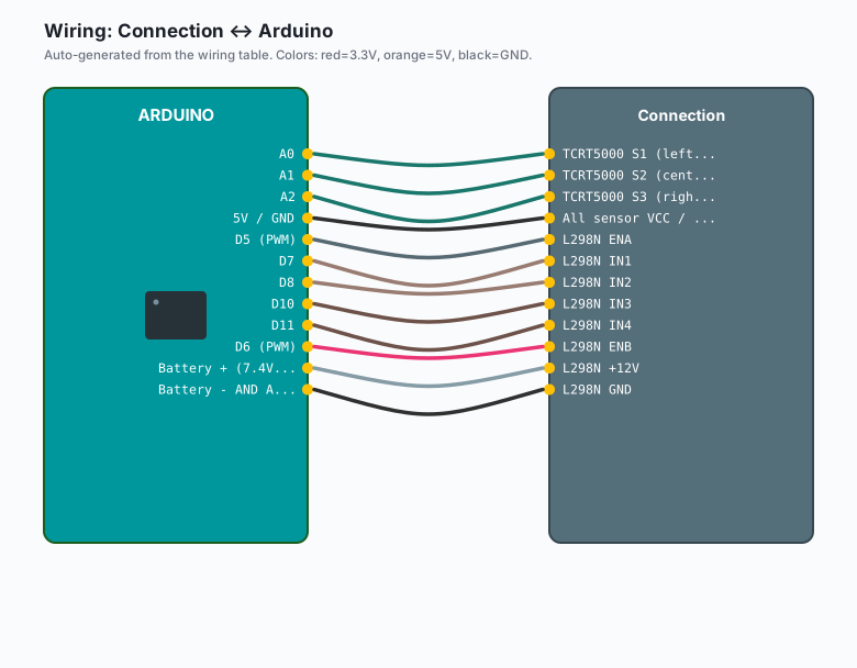
Wiring
| Connection | Arduino |
|---|---|
| TCRT5000 S1 (left) AO | A0 |
| TCRT5000 S2 (center) AO | A1 |
| TCRT5000 S3 (right) AO | A2 |
All sensor VCC / GND | 5V / GND |
| L298N ENA | D5 (PWM) |
| L298N IN1 | D7 |
| L298N IN2 | D8 |
| L298N IN3 | D10 |
| L298N IN4 | D11 |
| L298N ENB | D6 (PWM) |
| L298N +12V | Battery + (7.4V) |
L298N GND | Battery - AND Arduino GND (common ground, always) |
Mount the three sensors on the front edge of the chassis, 15 mm apart, about 5 mm above the floor. Clearance matters more than anything else in this build: too high and the black line vanishes, too low and the board drags.
Install
No library. You do want the serial plotter for tuning: Arduino IDE >> Tools >> Serial Plotter, 115200 baud. Upload the sketch with the wheels off the ground first (e.g. prop the chassis on two cups), watch the error trace while you slide the line under the sensors by hand, and only then set it on the floor.
The code
// PID line follower: analog TCRT5000 array, weighted position, fixed Ts.
const int SENSOR[3] = {A0, A1, A2};          // left, center, right
const int ENA = 5, IN1 = 7, IN2 = 8;
const int IN3 = 10, IN4 = 11, ENB = 6;

const float KP = 60.0;    // counts of PWM per unit of error
const float KI = 0.4;     // start at 0 while tuning KP, add last
const float KD = 350.0;   // damping; raise if it overshoots corners
const int   BASE = 120;   // cruising PWM, 0-255
const unsigned long TS = 10;  // control step, ms

float iErr = 0, ePrev = 0;
unsigned long tPrev = 0;

float readError() {
  float num = 0, den = 0;
  for (int i = 0; i < 3; i++) {
    float dark = 1023.0 - analogRead(SENSOR[i]); // white floor ~low, line ~high
    num += dark * (i - 1);                       // weights: -1, 0, +1
    den += dark;
  }
  if (den < 150.0) return ePrev;   // lost the line: hold the last steering
  return num / den;                // -1 (line left) .. +1 (line right)
}

void drive(float u) {
  digitalWrite(IN1, HIGH); digitalWrite(IN2, LOW);   // left forward
  digitalWrite(IN3, HIGH); digitalWrite(IN4, LOW);   // right forward
  analogWrite(ENA, constrain(BASE + u, 0, 255));     // u < 0 -> turn left
  analogWrite(ENB, constrain(BASE - u, 0, 255));     // u > 0 -> turn right
}

void loop() {
  unsigned long t = millis();
  if (t - tPrev < TS) return;      // fixed sample time: gains mean the same
  tPrev = t;                       // thing every run, not "whenever"

  float e = readError();
  iErr = constrain(iErr + e * TS, -2000.0, 2000.0);  // anti-windup clamp
  float d = (e - ePrev) * (1000.0 / TS);
  float u = KP * e + KI * iErr + KD * d;
  ePrev = e;
  drive(u);
}
If your modules happen to read low on the line and high on white, drop the
1023.0 - inversion; that single line is the whole calibration decision.
Check it once with the plotter and move on.
What you learned
- A weighted average of three analog channels is a position estimate, not a yes/no: this is what makes proportional control possible.
- A fixed sample time (millis-gated) is what makes your gains portable between test runs; with loop-rate control, the gains change every time you add a Serial print.
- Anti-windup is not optional once Ki exists: an unclamped integral winds up during a long corner and then slams the steering.
When something breaks
- Oscillates hard around the line: KP too high, or KD near zero. Back KP off 30 percent, then add KD until the wobble damps.
- Cuts corners, loses the line on curves: BASE is too high for the track. Drop it to 90, retune KP, then raise it back up in steps.
- Follows the edge of the tape: error sign is inverted (or left and
right sensors are swapped). Flip the sign of
uindrive()and see if the behavior reverses; that isolates wiring from math. - Fine on the bench, drunk on carpet: TCRT5000 hates carpet’s scattered IR. Hard floor, or raise clearance to 5-6 mm and retune the darkness floor.
- Motors stall at low PWM: L298N dropout plus a tired battery. Measure the battery under load; under 7V, charge or replace the 18650s.
- One sensor reads nonsense: its potentiometer is saturated, or the AO wire is in the wrong A-pin. Check with the plotter, one sensor at a time.
What to build next
- The bang-bang line-follower is the version to build with kids first: same chassis, half the concepts, and it makes this one feel earned.
- Add a front-facing HC-SR04 and stop at obstacles: the PID loop keeps steering while a simple guard gates the speed.
- The traffic light tutorial is the state-machine refresher for the lost-line behavior (coast, search, stop).
- The ESP32 robot base post is this same idea with Wi-Fi telemetry on top, when you want the error trace on a dashboard instead of the plotter.