ESP32: read bridge sensors with the ADS1115 in differential mode
Go past basic ADS1115 single-ended reads: differential inputs for bridge sensors, the PGA gain math, and a data-rate benchmark you can run yourself.
The other ADS1115 tutorial on this site gets the chip wired and reading a potentiometer. This one starts where that one stops: differential mode, the feature that makes the $4 chip worth owning. Bridge sensors (load cells, pressure cells, strain gauges, RTD bridges) do not output a voltage relative to ground. They output a voltage BETWEEN two wires, a few millivolts tall, and both wires wobble around together in the noise. A single-ended read measures one wire and the noise; a differential read measures the gap between the wires and the common noise cancels.
The trap: I wired my first bridge sensor to A0 and A1, called
readADC_Differential_0_1(), and got a number that moved with weight
but made no sense. It made no sense because the gain was still the
default. The default gain (GAIN_TWOTHIRDS, a ±6.144 V range) spreads
32768 counts across 12 volts of range. My bridge signal was 20 mV
tall, which is 0.16% of that window. Do the math in the other order
and the same signal with the right gain lands where the resolution
actually is. Getting gain right is not a settings detail; it is the
difference between 200 usable counts and 2000.
What you need
Needed
| Item | Qty | Purpose | Est. cost |
|---|---|---|---|
| ESP32 dev board | 1 | the brain | $8-$15 |
| ADS1115 breakout (Adafruit or GY-ADS1115) | 1 | 16-bit ADC with PGA | $4 |
| A bridge-type sensor to read | 1 | the differential signal source | varies |
| Jumper wires | 6 | I2C + sensor connections | $2 |
Bridge sensors in the wild: a bare load cell (four wires: E+, E-, A+, A-), a strain gauge glued to a lever, or an instrumentation-amp module that outputs a small differential pair. For bench testing without a sensor, a 10k potentiometer wired as a voltage divider with a resistor in series with the wiper imitates one well enough to prove the wiring.
Nice to have
- Multimeter to measure the bridge’s actual output span before you pick a gain (two minutes that save an hour)
- Breadboard and wire stripper for a clean, short sensor run
- Anti-static wristband: the ADS1115’s front end is a sensitive analog part worth the two seconds of caution
- Soldering iron and solder if your breakout came with an unsoldered header
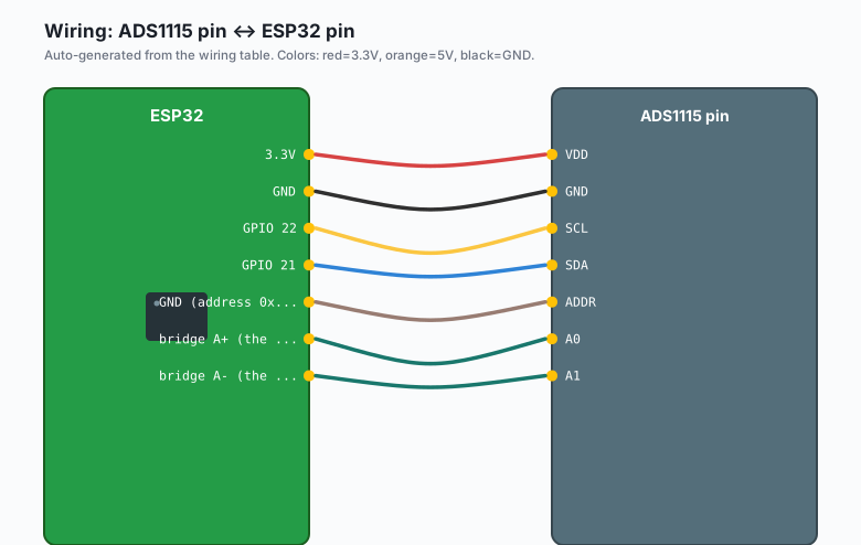
Wiring (I2C)
| ADS1115 pin | ESP32 pin |
|---|---|
| VDD | 3.3V |
GND | GND |
SCL | GPIO 22 |
SDA | GPIO 21 |
| ADDR | GND (address 0x48) |
A0 | bridge A+ (the amplifier output) |
A1 | bridge A- (the reference side) |
A differential read only ever uses pin pairs: A0-A1 or A2-A3. The chip has one PGA and one converter, so both pairs share the same gain.
Keep the chip at 3.3V. The ADS1115’s absolute input range is GND-0.3V to VDD+0.3V, so 5V signals damage it. Powering from 3.3V keeps every input ESP32-safe, and the gain settings below still cover mV-scale signals with room to spare.
Install
Arduino IDE >> Sketch >> Include Library >> Manage Libraries >> search “ADS1X15” >> install Adafruit ADS1X15. If you already installed it for the other tutorial, you are done; same library, different calls.
The gain math, done once
The PGA sets the full-scale range. One number decides how much of the 16 bits you actually get to use:
| Gain | Full-scale | One LSB | Right for |
|---|---|---|---|
| GAIN_TWOTHIRDS | ±6.144 V | 188 µV | 5 V signals |
| GAIN_ONE | ±4.096 V | 125 µV | most 3.3 V signals |
| GAIN_TWO | ±2.048 V | 62.5 µV | larger bridge amps |
| GAIN_FOUR | ±1.024 V | 31.25 µV | thermocouple amps, shunts |
| GAIN_EIGHT | ±0.512 V | 15.625 µV | bare strain gauges |
| GAIN_SIXTEEN | ±0.256 V | 7.8125 µV | load cells, mV signals |
The rule: pick the smallest range your signal cannot exceed, including its transients. A load cell excited at 5 V with 1 mV/V sensitivity outputs 5 mV at full load. GAIN_SIXTEEN covers ±256 mV, which is overkill until you remember the signal swings both ways during overload, taring, and vibration; at GAIN_SIXTEEN that 5 mV becomes about 640 counts of real resolution. At the default gain it becomes 27. Same sensor, same chip, one setting apart.
Two honest caveats. The ±6.144 V figure is the datasheet’s scaling reference, not an input guarantee: with the chip powered at 3.3V no input may exceed 3.6 V regardless of gain. And the useful resolution of the whole chain is bounded by your sensor, not the converter (e.g. a noisy bench build usually delivers 14 to 15 effective bits, not the full 16; plan around 13 solid bits and you will never be disappointed).
The code
#include <Wire.h>
#include <Adafruit_ADS1X15.h>

Adafruit_ADS1115 ads;

const float BRIDGE_SENS_MV_PER_V = 1.0;   // from the sensor's datasheet
const float BRIDGE_EXCITATION_V  = 5.0;   // what actually powers the bridge
const float FULL_LOAD_UNITS      = 5000;  // e.g. grams the full-scale load is

void setup() {
  Serial.begin(115200);
  Wire.begin(21, 22);

  if (!ads.begin(0x48)) {
    Serial.println("ADS1115 not found, check wiring");
    while (1) delay(1000);
  }

  ads.setGain(GAIN_SIXTEEN);            // ±0.256 V, one LSB = 7.8125 µV
  ads.setDataRate(RATE_ADS1115_8SPS);   // slowest = cleanest for weight
}

void loop() {
  int32_t sum = 0;
  const int n = 8;
  for (int i = 0; i < n; i++) {
    sum += ads.readADC_Differential_0_1();   // blocks ~125 ms at 8 SPS
  }
  float raw = sum / (float)n;

  float volts = raw * 0.0078125 / 1000.0;    // LSB in µV -> mV -> V
  float signal_mv = volts * 1000.0;
  // Bridge math: signal_mV = sensitivity(mV/V) * excitation(V) * load fraction
  float units = (signal_mv / (BRIDGE_SENS_MV_PER_V * BRIDGE_EXCITATION_V)) * FULL_LOAD_UNITS;

  Serial.printf("raw %.1f  %.3f mV  %.1f g\n", raw, signal_mv, units);
  delay(500);
}
That 8-sample average is not decoration. At 8 SPS the chip is already heavily averaged internally, but the outer average removes the residual wobble you will see in the last digit.
Benchmark the data rates yourself
The ADS1115 runs at 8, 16, 32, 64, 128, 250, 475, or 860 samples per second. Faster means noisier (the chip spends less time integrating each sample) and slower means smoother. Do not take my word for it; measure it. This sketch prints actual throughput and the standard deviation of a fixed input:
#include <Wire.h>
#include <Adafruit_ADS1X15.h>

Adafruit_ADS1115 ads;

const uint16_t rates[] = {
  RATE_ADS1115_8SPS, RATE_ADS1115_16SPS, RATE_ADS1115_32SPS,
  RATE_ADS1115_64SPS, RATE_ADS1115_128SPS, RATE_ADS1115_250SPS,
  RATE_ADS1115_475SPS, RATE_ADS1115_860SPS
};
const char* names[] = {"8", "16", "32", "64", "128", "250", "475", "860"};

void setup() {
  Serial.begin(115200);
  Wire.begin(21, 22);
  ads.begin(0x48);
  ads.setGain(GAIN_SIXTEEN);
}

void loop() {
  for (int r = 0; r < 8; r++) {
    ads.setDataRate(rates[r]);

    const int n = 100;
    int32_t sum = 0;
    float samples[100];
    uint32_t t0 = micros();

    for (int i = 0; i < n; i++) {
      samples[i] = ads.readADC_Differential_0_1();
      sum += samples[i];
    }
    uint32_t elapsed = micros() - t0;

    float mean = sum / (float)n;
    float var = 0;
    for (int i = 0; i < n; i++) var += (samples[i] - mean) * (samples[i] - mean);
    float sigma = sqrt(var / n);

    Serial.printf("%4s SPS: measured %5.1f SPS, sigma %.2f LSB\n",
                  names[r], n * (1000000.0 / elapsed), sigma);
    delay(200);
  }
  Serial.println("---");
  delay(3000);
}
Wire A0 and A1 to a fixed divider (two resistors, or just both to GND through 10k) so the input is stable, then watch what the numbers do. Typical results on a clean 3.3V bench: sigma under 1 LSB at 8 SPS, about 2 to 3 LSB at 128 SPS, and 6 to 10 LSB at 860 SPS. The right setting is the fastest one whose noise your project tolerates (e.g. a scale wants 8 or 16 SPS, a vibration logger wants 860).
One more trick for slow rates: 8 SPS does not mean your loop must wait 125 ms per read. Read A0-A1 at 860 SPS and A2-A3 at 8 SPS only when you need the smooth value; the multiplexer switches between pairs without touching the rate register.
What you learned
- Differential mode measures the gap between two wires, so noise that moves both wires together cancels. Bridge sensors require it.
- Gain selection is resolution allocation: full-scale range over 32768 decides your LSB size, and the smallest safe range wins.
- Data rate is a noise/speed trade you can measure in one sketch, and the sigma numbers tell you which rate your project can live with.
When something breaks
- Raw reads pegged at 32767 or -32768: the signal exceeds the gain range. Drop one gain step (bigger range) or scale the bridge down.
- Raw reads near 0 and will not move: the two bridge wires are on the same pair but the bridge is not excited. Check E+ and E- have real voltage across them, and that A+ / A- are the amplifier outputs, not the excitation wires.
- Readings swing wildly with a hand near the wires: your sensor run is long and unshielded. Twist the A+/A- pair, shorten the run, and ground the shield if the cable has one.
- The benchmark shows sigma worse than the table above: your breadboard ground is shared with a noisy device (e.g. a relay or motor driver on the same rail). Give the ADS1115 its own ground path to the ESP32.
- The library’s
computeVolts()disagrees with your number: it computes from the CURRENT gain; if you changed gain after the read, the volts are wrong. Read, then convert, in that order.
What to build next
- The ESP32 weight scale (HX711) tutorial is the dedicated-amp version of this build; the ADS1115 differential path is the general-purpose equivalent when you also need other channels.
- Pair this with MQTT publishing (the tutorial on this site covers it) and the scale’s grams become a graph on a dashboard.
- The oscilloscope basics tutorial shows how to see the noise you just measured with sigma; the two skills reinforce each other.
- The ADS1115 external ADC tutorial covers single-ended reads, the four I2C addresses, and the basics this one skipped.
The book IoT with ESP32 bundles the sensor tutorials including this one.