Arduino: build a gas alarm with the MQ-2
Build an MQ-2 gas and smoke alarm on an Arduino: wiring, warm-up, calibration, buzzer code, and the honest limits of a DIY detector.
The MQ-2 is the cheapest way to give an Arduino a nose. It reacts to smoke, LPG, propane, methane, butane, and a long list of combustible gases, it costs about $3, and this build turns it into a loud bench alarm: gas over the threshold, the buzzer screams, an LED blinks, and the serial log keeps score.
The trap is the warm-up. The MQ-2 is a heated tin-oxide element, and it needs 24 to 48 hours of powered burn-in before its baseline settles (e.g. mine read 340 “units” in clean air on day one, 190 by day two, then stopped drifting). Calibrate on day one and you have calibrated noise. Plug it in, leave it powered on the bench overnight, then set your threshold.
One more thing before the wiring, said plainly: this is a learning project, not a certified smoke detector. Keep the real smoke alarms in the house. This build is for a soldering-iron bench, a workshop corner, or a kitchen experiment, places where a loud “go look at that” alarm is useful and nobody’s life depends on it.
What you need
Needed
- Arduino Uno or Nano (the Nano is the same code on a smaller board)
- MQ-2 gas sensor module, 4-pin breakout (about $3; get the version with both DO and AO pins, you will use both)
- Active 5V buzzer (about $1; “active” means it beeps on a plain HIGH, no tone() waveform needed)
- Red LED and a 220 ohm resistor (the alarm light)
- Breadboard and jumper wires
Why the module and not the bare sensor: the breakout carries the load resistor, the heater regulator, and the LM393 comparator. Wiring a bare MQ-2 can is a different, fiddlier project.
Nice to have
- Soldering iron and solder, plus a stand and helping hands (if the module ships with bare headers)
- Wire stripper and a multimeter (check the 5V rail and buzzer polarity)
- Anti-static wristband, magnifying goggles, and a soldering mat (the standard workshop layer)
- A window or a small fan: you will release test gas, and you want it gone
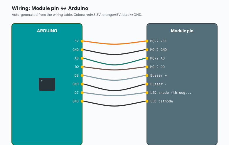
Wiring
| Module pin | Arduino |
|---|---|
MQ-2 VCC | 5V |
MQ-2 GND | GND |
| MQ-2 AO | A0 |
| MQ-2 DO | D2 |
| Buzzer + | D8 |
| Buzzer - | GND |
| LED anode (through 220 ohm) | D7 |
| LED cathode | GND |
The MQ-2 heater draws about 150 mA, continuously, forever. USB power is fine for that. A weak battery pack is not: the heater sags the rail, and your readings wander with it. Power from USB or a proper 5V supply.
Install
No library is needed, which is a nice change. Confirm the board selection (Arduino IDE >> Tools >> Board >> Arduino Uno), upload the sketch, then open the serial monitor (Arduino IDE >> Tools >> Serial Monitor, 9600 baud).
The code
// MQ-2 gas alarm: analog reading for the trend, digital pin as the
// module's own comparator. Buzzer + LED on alarm.
const int PIN_AO   = A0;
const int PIN_DO   = 2;
const int PIN_BUZZ = 8;
const int PIN_LED  = 7;
const int THRESHOLD = 300;   // set this from YOUR baseline, see below

void setup() {
  Serial.begin(9600);
  pinMode(PIN_DO, INPUT);
  pinMode(PIN_BUZZ, OUTPUT);
  pinMode(PIN_LED, OUTPUT);
  Serial.println("Warming up; readings drift for the first minutes after power-on.");
}

void loop() {
  int raw = analogRead(PIN_AO);
  int dig = digitalRead(PIN_DO);   // most blue LM393 boards go LOW on gas;
                                   // if yours is inverted, flip this test
  Serial.print("analog: ");
  Serial.print(raw);
  Serial.print("   digital: ");
  Serial.println(dig);

  bool gas = (raw > THRESHOLD) || (dig == LOW);
  if (gas) {
    digitalWrite(PIN_BUZZ, HIGH);
    digitalWrite(PIN_LED, HIGH);
    delay(200);
    digitalWrite(PIN_BUZZ, LOW);
    digitalWrite(PIN_LED, LOW);
  }
  delay(300);
}
Calibration is two numbers. After the 24-48 h burn-in, read the clean-air
baseline from the serial monitor, add about 100, and put that in
THRESHOLD. Then test: hold an unlit lighter 20 cm away, press the gas
release for one second (no flame, never a flame near the bench), and watch
the reading jump.
What you learned
- Heated metal-oxide sensors work by resistance change: gas drops the resistance, the module turns that into a voltage, the ADC reads it.
- The module gives you two answers: AO (how much, roughly) and DO (the onboard comparator’s own yes/no, set by its potentiometer).
- Warm-up and a clean-air baseline are part of the measurement, not setup chores you can skip.
When something breaks
- Readings never settle: you are still in warm-up, or the module is on 3.3V. The heater wants a real 5V; half-heated sensors drift forever.
- Alarm fires in clean air: the threshold is too close to the baseline, or the DO potentiometer is set wrong. Turn the pot until the module’s own DO LED sits just off in clean air, then re-run.
- No reaction to test gas: AO and VCC are swapped, or the butane puff never reached the sensor. Test from 20 cm, and give the reading a few seconds to climb.
- Buzzer silent but LED blinks: you have a passive buzzer, which needs tone(PIN_BUZZ, 2000) instead of a plain HIGH. Or the buzzer leads are reversed; swap them.
- Wild spikes on the log: breadboard contact or a sagging supply. For a permanent install, solder the sensor leads and feed the heater from its own 5V wire, not a shared breadboard rail.
What to build next
- Swap the buzzer pattern for a relay and a floodlight: the night security light tutorial is the same threshold logic with a bigger output.
- Turn the alarm into a staged state machine (clean, warning, alarm) with the traffic light tutorial’s three-LED pattern.
- The ESP32 sibling post (esp32 MQ-2) sends the same alarm to your phone over MQTT or ntfy, both self-hosted, no cloud account in sight.