Pico: drive DC motors with the L298N
Wire a Pico to an L298N motor driver, drive one or two DC motors with PWM speed control in MicroPython, and get direction control for free. The start of every wheeled robot.
A Pico GPIO pin can light an LED, but a DC motor would kill it. A small yellow TT motor wants 200 mA and the GPIO pins top out around 12 mA, so the pin would sag, the motor would stall, and the Pico would brown out into a reboot loop. The L298N motor driver sits in between: the Pico sends small signals, the L298N sends big current to the motor.
I built a two-wheeled robot on a Pico with this exact setup, and the trap I hit on day one was power, not code. I powered the motors from the Pico’s VBUS pin, the motor stall current dragged the 5V rail down, and the Pico reset every time the robot hit a wall. Motors do not stall politely. They stall at 10x their running current, at the exact moment your code asks for maximum torque. Separate supplies or a big capacitor, pick one. Actually, pick both.
What you need
Needed
- Raspberry Pi Pico
- L298N motor driver board (the red 2-channel one with the blue terminal
- 2 DC gear motors, the yellow “TT” type with the double-axis gearbox,
- 6 AA battery holder with a barrel jack or wire leads, for motor power
- Jumper wires, both male-female and male-male
- A 100 uF electrolytic capacitor across the motor power input (the L298N
Nice to have
- A soldering iron and solder (only if you solder the header pins yourself)
- Helping hands or a vise to hold the board while you work
- An anti-static wristband (cheap insurance for the RP2040)
Wiring
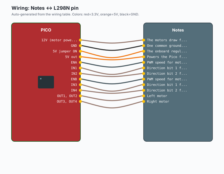
The L298N has two sides: the logic side (EN, IN1-4, and the 5V/GND for the onboard regulator) and the motor side (OUT1/OUT2 and OUT3/OUT4).
| L298N pin | Connect to | Notes |
|---|---|---|
| 12V (motor power in) | Battery + (6 AA holder) | The motors draw from here, not from the Pico |
GND | Battery - AND Pico GND | One common ground for everything |
5V jumper ON | (leave jumper installed) | The onboard regulator makes 5V from the battery |
5V out | Pico VBUS | Powers the Pico from the same battery |
| ENA | GPIO 14 | PWM speed for motor A |
| IN1 | GPIO 15 | Direction bit 1 for motor A |
| IN2 | GPIO 16 | Direction bit 2 for motor A |
| ENB | GPIO 17 | PWM speed for motor B |
| IN3 | GPIO 18 | Direction bit 1 for motor B |
| IN4 | GPIO 19 | Direction bit 2 for motor B |
| OUT1, OUT2 | Motor A terminals | Left motor |
| OUT3, OUT4 | Motor B terminals | Right motor |
If one motor spins the wrong way, swap its two output wires. There is no software fix for “I wired the motor backwards”; there is only “swap the wires in two seconds and move on.”
Do not power the motors from the Pico’s VBUS or 3V3 pins. The stall current of a TT motor is 1A or more per motor and the Pico cannot source it. This is the brownout-reset loop, and it took me an evening to diagnose because it looked like a firmware bug.
Install
Nothing to install. The L298N takes plain GPIO and plain PWM, both of which MicroPython speaks natively. No library, no pip, no mip. This is the whole reason I recommend it to people starting out.
The code
One motor first, because two motors with a wiring mistake is twice the
debugging. Save this as main.py on the Pico:
from machine import Pin, PWM
import time

# Motor A on the L298N
ena = PWM(Pin(14))    # speed pin (EN_A)
in1 = Pin(15, Pin.OUT)
in2 = Pin(16, Pin.OUT)

ena.freq(1000)        # 25 kHz would be even quieter; 1 kHz is fine for TT motors

def drive(speed, forward=True):
    # speed: 0-65535 duty_u16
    in1.value(1 if forward else 0)
    in2.value(0 if forward else 1)
    ena.duty_u16(speed)

def stop():
    in1.value(0)
    in2.value(0)
    ena.duty_u16(0)

# Spin forward at 60% for 2 seconds
drive(int(65535 * 0.6), forward=True)
time.sleep(2)

# Coast to a stop
stop()

# Reverse at 60% for 2 seconds
drive(int(65535 * 0.6), forward=False)
time.sleep(2)
stop()
The IN1/IN2 pair is the direction, ENA is the throttle. Four combinations to know:
| IN1 | IN2 | Result |
|---|---|---|
| 0 | 0 | Coast (motor spins freely) |
| 0 | 1 | Reverse |
| 1 | 0 | Forward |
| 1 | 1 | Brake (motor shorted, stops hard) |
Brake versus coast matters for a robot that needs to stop on a slope. The brake pattern (both IN pins high) shorts the motor windings together, and the back-EMF turns into braking torque. Coast just lets it roll.
Both motors and a tank-turn
Here is the two-motor version with a differential-drive pattern:
from machine import Pin, PWM
import time

class Motor:
    def __init__(self, en, in1, in2):
        self.pwm = PWM(Pin(en))
        self.pwm.freq(1000)
        self.in1 = Pin(in1, Pin.OUT)
        self.in2 = Pin(in2, Pin.OUT)

    def drive(self, speed, forward=True):
        self.in1.value(1 if forward else 0)
        self.in2.value(0 if forward else 1)
        self.pwm.duty_u16(max(0, min(65535, speed)))

    def stop(self):
        self.in1.value(0)
        self.in2.value(0)
        self.pwm.duty_u16(0)

left = Motor(14, 15, 16)
right = Motor(17, 18, 19)

def tank(left_speed, right_speed):
    # speeds in -65535..65535; sign is direction
    left.drive(abs(left_speed), left_speed >= 0)
    right.drive(abs(right_speed), right_speed >= 0)

# Forward
tank(40000, 40000)
time.sleep(2)

# Spin in place (one forward, one reverse)
tank(40000, -40000)
time.sleep(1)

# Stop
tank(0, 0)
Negative speed means reverse, so tank(40000, -40000) is a spin-in-place
tank turn. This class is the one I copy into every Pico robot project.
Speed, stall current, and the brownout trap
A TT motor runs at about 200 mA and stalls at 1A or more. The L298N drops about 2V of the battery voltage across its own transistors (this is the “inefficient” part I mentioned), so a 7.2V battery pack gives the motors about 5V at the terminals. Six AA alkaline cells in series are 9V fresh and sag under load; six NiMH cells are 7.2V and hold up better. If your robot resets when it hits an obstacle, that is the brownout trap, and the fix is a bigger battery (NiMH instead of alkaline) or a capacitor bank on the motor supply.
What you learned
- GPIO pins cannot drive motors directly; the L298N is the muscle and the Pico is the brain.
- IN1/IN2 set direction, ENA/ENB set speed with PWM.
- Motor power and logic power are separate rails on the L298N; the only wire they share is ground.
- The brake pattern (both IN pins high) is a real thing and useful.
When something breaks
- The Pico resets when the motors spin up. You are back-feeding the Pico through the motor supply, or the battery cannot handle the stall current. Check the 5V jumper: with the jumper on, the L298N’s regulator powers the Pico through the 5V pin, and the motor battery handles the motors. Also add the 100 uF capacitor if you skipped it.
- One motor spins, the other does nothing. The ENB jumper on the L298N board. Some boards ship with ENA and ENB jumped to 5V (always full speed); if yours still has the jumper on ENB, your GPIO 17 signal goes nowhere. Pull the jumper, wire both enable pins to the Pico.
- Motors run at full speed no matter the duty cycle. Same cause, same fix: the enable jumper is still on. Pull it.
- The motor buzzes but does not turn. The battery is too weak (AA alkaline cells sag under load), or the L298N’s 2V drop plus a weak battery leaves less than the motor’s minimum. Try NiMH cells, or a 7.4V 2S LiPo with the right charger.
PWM(Pin(14))throwsValueError. GPIO 14 is fine, but check you did not typo the pin into the 40-pin header count (physical pin 19 is GPIO 14). Count from the GPIO number, not the physical pin.
What to build next
- The Pico servo tutorial covers the other motor type; a pan/tilt mount is servos, a drivetrain is DC motors, and the two together are a camera robot.
- The Pico asyncio tutorial runs the motor control loop, a status LED, and a sensor read at the same time without stepping on each other.
- The Pico microSD datalogger records motor current over time so you can see the stall events instead of guessing.