ESP32: talk to GPS, GSM, or another MCU over UART2
Wire a GPS, GSM, or second microcontroller to the ESP32 over UART2, with working pins, the TX/RX cross, and non-blocking code that parses what comes back.
The GPS module sat on my desk spitting perfect NMEA sentences into the void for ten minutes before I figured out the problem. The wiring was fine. The code was fine. The baud rate was fine. The TX wire was going from the GPS’s TX pin to the ESP32’s TX pin, which means both devices were shouting into a wire that neither was listening to. Two transmitters on one wire receive nothing. That is the whole lesson of UART in one paragraph.
UART is the protocol for chip-to-chip chat when the other chip streams data at you: GPS modules, GSM modems (SIM800L, SIM7600), Bluetooth bridges (HC-05), RFID readers, Nextion displays, or a second microcontroller. Two data wires plus ground. No addresses, no registers, no clock line. One side transmits, the other receives, and the baud rate is the only thing they have to agree on.
The trap: the ESP32 has three hardware UARTs and beginners reach for the wrong one. UART0 is wired to the USB-serial chip that uploads your sketches and prints your Serial Monitor output. Share it with a GPS and the GPS’s NMEA noise floods the upload path (e.g. a module that transmits every second can garble the boot messages and sometimes blocks flashing entirely). UART2 is the free one, and on standard dev boards it lands on GPIO 16 (RX2) and GPIO 17 (TX2).
What you need
Needed
- ESP32 dev board (ESP32-DevKitC or a DOIT clone, about $8).
- One UART device to talk to. Pick one:
- NEO-6M or NEO-M8N GPS module (about $10-15), for the location demo.
- SIM800L GSM module (about $10) with a separate 3.7-4.2 V supply; the module brownouts the ESP32 if you power it from the dev board’s 3V3 pin.
- A second ESP32 or Arduino as the other end, for the chip-to-chip demo.
- 4 jumper wires, female-female (most breakouts have male headers).
Nice to have
- Soldering iron + solder, if your module ships with a bare header strip.
- Soldering iron stand, for parking the hot iron between joints.
- Helping hands, to hold the header straight while it cools.
- Anti-static wristband, for handling bare GSM modules.
- Magnifying goggles, for reading the pin silkscreen on cheap breakouts (some label RX where they mean TX).
- Soldering mat, to keep solder splashes off the desk.
- Wire stripper, for power leads to the SIM800L.
- Multimeter, to confirm 4 V actually reaches the GSM module under load.
Wiring
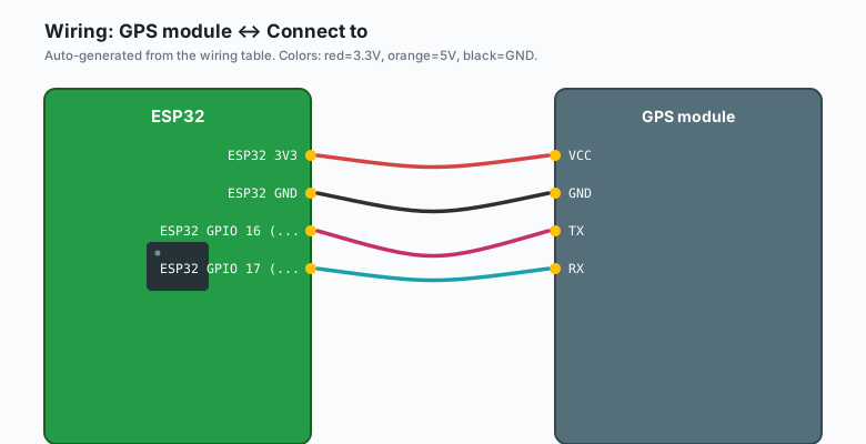
Serial is always crossed: my TX into your RX, my RX into your TX.
| GPS module | Connect to |
|---|---|
VCC | ESP32 3V3 |
GND | ESP32 GND |
TX | ESP32 GPIO 16 (RX2) |
RX | ESP32 GPIO 17 (TX2) |
| Chip-to-chip (ESP32 to ESP32) | Connect to |
|---|---|
Board A GPIO 17 (TX2) | Board B GPIO 16 (RX2) |
Board A GPIO 16 (RX2) | Board B GPIO 17 (TX2) |
Board A GND | Board B GND |
The ground wire is not optional. Two devices on separate power supplies have no common voltage reference without it, and the data line reads as random garbage. Every “UART is unreliable” bug I have seen was a missing ground or a swapped TX/RX.
A SIM800L draws up to 2 A bursts during transmit. It will reset the ESP32’s regulator if you share the supply. Give it its own 3.7 V lithium cell or a bench supply, and tie the grounds together.
Install
Arduino IDE >> Sketch >> Include Library >> Manage Libraries >> search “TinyGPSPlus” >> install (Mikal Hart’s TinyGPSPlus). It handles NMEA checksums and does not block your loop. For the SIM800L path, no library is required: the modem speaks plain AT commands over the serial line, and the code below sends them directly.
The code
GPS over UART2 (Arduino)
#include <TinyGPSPlus.h>
#include <HardwareSerial.h>

TinyGPSPlus gps;
HardwareSerial GPSSerial(2);   // UART2: RX2 = GPIO 16, TX2 = GPIO 17

void setup() {
  Serial.begin(115200);
  delay(1000);
  GPSSerial.begin(9600, SERIAL_8N1, 16, 17);   // RX=16, TX=17
  Serial.println("Waiting for fix (go near a window)...");
}

void loop() {
  // Feed every arrived byte to the parser, never wait
  while (GPSSerial.available() > 0) {
    gps.encode(GPSSerial.read());
  }

  static unsigned long lastPrint = 0;
  if (millis() - lastPrint > 1000) {
    lastPrint = millis();
    if (gps.location.isValid()) {
      Serial.print("Lat: ");
      Serial.print(gps.location.lat(), 6);
      Serial.print("  Lng: ");
      Serial.print(gps.location.lng(), 6);
      Serial.print("  Sats: ");
      Serial.println(gps.satellites.value());
    } else {
      Serial.println("No fix yet.");
    }
  }
}
The shape of this loop matters. You never “ask the GPS for data.” The
module streams continuously; you drain the buffer every pass through
loop() and check the parsed result whenever you feel like it. That is
the non-blocking UART pattern, and it is the difference between this
sketch and one that freezes while waiting for a sentence.
Chip-to-chip: two ESP32s (or an ESP32 and an Arduino)
Sender (the board doing the talking):
#include <HardwareSerial.h>

HardwareSerial PeerSerial(2);

void setup() {
  Serial.begin(115200);
  PeerSerial.begin(115200, SERIAL_8N1, 16, 17);   // RX=16, TX=17
}

unsigned long lastSend = 0;
int n = 0;

void loop() {
  if (millis() - lastSend > 2000) {
    lastSend = millis();
    n++;
    PeerSerial.print("hello ");
    PeerSerial.println(n);
    Serial.print("sent: hello ");
    Serial.println(n);
  }
}
Receiver (the board doing the listening):
#include <HardwareSerial.h>

HardwareSerial PeerSerial(2);

void setup() {
  Serial.begin(115200);
  PeerSerial.begin(115200, SERIAL_8N1, 16, 17);
}

void loop() {
  if (PeerSerial.available()) {
    String line = PeerSerial.readStringUntil('\n');
    line.trim();
    if (line.length() > 0) {
      Serial.print("got: ");
      Serial.println(line);
    }
  }
}
Line-oriented framing (print on one side,
readStringUntil('\n') on the other) is the simplest reliable scheme
for MCU-to-MCU links. If you move binary data or variable-length
payloads, graduate to a length prefix or a checksum, but do not add
either until plain lines break.
GSM modems: AT commands over the same UART
A SIM800L is just a remote-controlled modem. You write an AT command,
it answers. The same HardwareSerial(2) object drives it, usually at
115200 baud:
// after GPSSerial-style init at 115200:
modemSerial.println("AT");              // handshake, expect "OK"
modemSerial.println("AT+CSQ");          // signal quality, expect "+CSQ: 15,0"
modemSerial.println("AT+CMGF=1");       // text mode for SMS
Read responses with the same non-blocking drain pattern as the GPS
example. Never write an AT command and blindly delay() past the
reply; collect the response and check for “OK” before sending the next
one.
Baud rate quick reference
| Device | Typical baud |
|---|---|
| GPS (NEO-6M / M8N) | 9600 |
| SIM800L / HC-05 | 9600 (HC-05) or 115200 (SIM800L) |
| Another ESP32 / Arduino | 115200 |
| Nextion display | 9600 default, 115200 after config |
Both ends must agree, and higher rates want shorter wires (under 30 cm at 115200 on jumper wires; 9600 tolerates a meter).
What you learned
- UART is two crossed wires and a shared ground. My TX to your RX, always.
- UART2 (GPIO 16/17) is the ESP32’s spare hardware serial port; UART0 belongs to the USB chip and should be left alone.
- The non-blocking pattern: drain
available()bytes every loop pass, parse, then act. Never sleep waiting for a serial device. - Line framing (
print/readStringUntil('\n')) is enough protocol for MCU-to-MCU chatter. - GPS, GSM, Bluetooth bridges, displays, and second MCUs are all the same pattern with different baud rates.
When something breaks
- Nothing comes in at all. TX and RX are swapped. The GPS’s TX must land on GPIO 16 (the ESP32’s receive pin). Swap the two signal wires and re-test. This is the number one UART bug, and it gets everyone more than once.
- Garbage characters instead of text. Baud rate mismatch. The sender and receiver disagree on bits per second. Confirm the rate in the device datasheet, and remember some GPS clones run 9600 while others run 115200 or 38400.
- Data appears only while you hold a wire. Missing common ground, or a jumper wire with a broken crimp. Tie both boards’ GND pins together directly and try a different jumper.
- Sketches will not upload with the module connected. You wired the device onto UART0 (GPIO 1/3). Move it to UART2. If the module transmits during flashing, the upload collides with it.
readStringUntilreturns partial lines. You are reading faster than the sender transmits. Either poll until the buffer has a newline, or switch to accumulating into a buffer and parsing when'\n'arrives (e.g. appendSerial.read()bytes to a String and check the last character).
What to build next
- The ESP32 GPS tutorial goes deep on NMEA parsing and UTC time from a NEO-M8N, using this exact wiring.
- The ntfy notifications tutorial pairs with a GSM modem for alerts from somewhere without Wi-Fi (e.g. the gate at the end of a long driveway).
- The ESP-NOW tutorial is the wireless alternative to the chip-to-chip link: same data, no wires, no baud rate.
- The MQTT publish-subscribe tutorial takes the data this UART link delivers and fans it out to every dashboard in the house.