ESP32: read sound level with an analog microphone module
Wire an analog microphone module (MAX4466 or LM393 sound sensor) to the ESP32's ADC and build an RMS sound level meter for clap triggers and noise logging.
The INMP441 I2S microphone tutorial is the good way to capture audio on an ESP32: digital, clean, one spare wire of noise. This tutorial is the cheap way, and sometimes cheap is the right tool. An analog mic module is one wire to one ADC pin, no I2S setup, and it answers the question most projects actually have: “how loud is it right now?” (e.g. clap-triggered lights, a fan that runs only while the shop tools run, a noise log for the room next to the nursery). If you only need a level and a threshold, a $2 analog module gets you there in twenty minutes.
The trap: people wire the module, print analogRead(), and get a
number that hovers around 2048 forever. That is the ADC idling at the
middle of the waveform, which is exactly what an audio signal is:
an oscillation around a midpoint, not a rising DC level. The fix is
computing the peak or RMS of a whole buffer of samples instead of
reading one sample per loop. The reading-per-loop mistake is the
number one reason analog mic tutorials “don’t work.”
What you need
Needed
| Item | Qty | Purpose | Est. cost |
|---|---|---|---|
| ESP32 dev board (WROOM-32 devkit) | 1 | reads the ADC, runs the level math | $10 |
| MAX4466 adjustable-gain mic module | 1 | electret capsule plus amplifier, gain pot on board | $3 |
| Jumper wires (3) | 3 | VCC, GND, OUT to ADC | $1 |
| Breadboard | 1 | holding the module while you test | $3 |
Why the MAX4466 over the even cheaper LM393-style sound sensor boards: the LM393 boards output a comparator signal (a square wave that flickers with sound), which answers “is there sound” but not “how loud”. The MAX4466 outputs the actual amplified waveform on its analog pin, so you can compute real levels, and it has a gain trimpot to match your room. (The LM393 boards also have an analog tap on some clones, but the MAX4466 is the one designed for it.)
Nice to have
- Multimeter: verify the module’s VCC and that its OUT idles near the midpoint voltage before the code looks at it.
- Soldering iron + solder: the MAX4466 usually ships with the header unsoldered.
- Helping hands, iron stand, soldering mat: the soldering support trio.
- Anti-static wristband: the electret capsule is happier not zapped.
- Magnifying goggles: the gain pot and pin labels are small.
- Wire stripper: for the permanent install.
Wiring
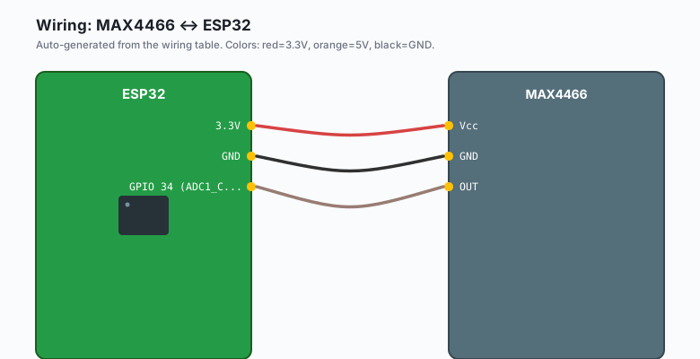
One signal wire. The analog pin is the whole interface.
| MAX4466 | ESP32 |
|---|---|
Vcc | 3.3V |
GND | GND |
| OUT | GPIO 34 (ADC1_CH6, input only) |
Use an ADC1 pin (GPIOs 32-39). The ADC2 pins (GPIOs 0, 2, 4, 12-15, 25-27) stop working whenever Wi-Fi is on, which is a surprise you do not want after you have already mounted the thing. GPIO 34-39 are input-only, which is fine because this module only outputs.
Keep the module a few centimeters off the breadboard rail that shares power with anything noisy. The mic hears its own power rail (e.g. a shared rail with an LED makes the LED’s ripple show up as a sound floor).
Install
Nothing to install. The ADC, the level math, and the Wi-Fi are all in the ESP32 core, so Arduino IDE >> Sketch >> Include Library >> Manage Libraries stays shut for this one.
The code
The sketch samples a window of audio, computes both peak and RMS, and thresholds the RMS for a clap trigger. RMS (square every sample, average, square root) is the honest “energy in this window” number; peak answers “did anything spike” and is what a click does its worst to.
const int MIC_PIN = 34;        // ADC1, input-only pin
const int SAMPLES = 2000;      // ~30 ms of audio at default ADC speed

void setup() {
  Serial.begin(115200);
  analogReadResolution(12);    // 0-4095
  Serial.println("analog mic level meter ready");
}

void loop() {
  uint64_t sumSquares = 0;
  int peak = 0;
  int midpoint = 2048;         // refine below from actual data

  // First pass: find the midpoint (DC bias) of this window
  int sum = 0;
  for (int i = 0; i < SAMPLES; i++) {
    sum += analogRead(MIC_PIN);
  }
  midpoint = sum / SAMPLES;

  // Second pass: peak and RMS around the midpoint
  for (int i = 0; i < SAMPLES; i++) {
    int v = analogRead(MIC_PIN) - midpoint;
    if (v < 0) v = -v;
    if (v > peak) peak = v;
    sumSquares += (int64_t)v * v;
  }
  float rms = sqrt((float)(sumSquares / SAMPLES));

  Serial.printf("peak: %4d  rms: %6.1f\n", peak, rms);

  if (rms > 300) {             // tune this to your room
    Serial.println("LOUD: clap detected");
    delay(1000);               // crude debounce
  }
  delay(50);
}
Upload it and open the Serial Monitor at 115200. A quiet room shows an RMS in the tens; talking near the module pushes it to hundreds; a clap spikes it past a thousand. The gain pot on the MAX4466 sets how much of the ADC range your room’s sounds use: turn it up for a whole-room meter, down for a clap trigger on a desk.
Two numbers worth knowing: two full-scale ADC references per loop
means about 25,000 reads per second at default settings, so the
30 ms window is honest audio sampling. And int64_t for
sumSquares is not optional paranoia: squaring 12-bit values
overflows a 32-bit int after a few hundred samples.
The threshold, honestly
Every room has a noise floor, and every mic module has a gain setting, so no tutorial can hand you the number. Watch the RMS output for a minute, note the quiet-room value, note the clap value, and pick a threshold between them with margin on the quiet side. Then log it for a day (the SD card datalogging tutorial is the natural partner) and adjust once. That is the whole tuning process, and it is the same for every sound sensor in every project.
What you learned
- An analog mic module is one wire to an ADC1 pin, and the whole
interface is
analogRead(). - One
analogRead()per loop is the classic mistake: audio is an oscillation around a midpoint, so you must window it and compute peak or RMS. - Peak for clicks, RMS for sustained sound; threshold the RMS with margin over your room’s measured floor.
- I2S (the INMP441 tutorial) is the upgrade path when you want actual audio, not just a level.
When something breaks
- The reading barely moves. You are reading once per loop (see the trap), or the gain pot is fully down, or the module’s OUT is not actually on your ADC1 pin. Window it first, then check gain.
- The level is maxed at 4096 constantly. Gain too high or the module’s amp is clipping: turn the trimpot down until a normal voice sits mid-range.
- Wi-Fi on, readings go flat. You are on an ADC2 pin. Move to GPIO 32-39; ADC2 loses to Wi-Fi by design, not by defect.
- Random triggers at night. The threshold sits too close to the noise floor, and the floor rises (an HVAC cycling on, a fridge). Raise the margin, or use a longer window so one blip cannot cross it.
- The module reads but sounds muffled or one-sided. The capsule hole is covered or facing the wall. These modules hear best through the little hole in the top of the capsule; do not bury it in hot glue.
What to build next
- The INMP441 I2S microphone tutorial is the digital upgrade: same room, real 16-bit audio, wake words and WAV captures instead of a level.
- The ESP32 SD card datalogging tutorial turns this meter into a noise logger with timestamps (the “how loud is the workshop really” project).
- The ntfy notifications tutorial turns the clap threshold into a phone alert (the back-door monitor: two claps means someone is in the garage).
- The MQTT publish-subscribe tutorial feeds the RMS level into
a home automation stack as
shop/noise/level.
The IoT with ESP32 book bundles both microphone tutorials with the logging and notification tutorials into a sound chapter.