ESP32: add 8 analog inputs over SPI with the MCP3008
The ESP32 loses half its ADC pins the moment Wi-Fi turns on. Add 8 clean analog inputs with a $4 MCP3008 over SPI: wiring, real pins, and a full 8-channel sketch.
The ESP32 datasheet advertises 18 analog inputs. Reality: ADC2 shares
its pins with Wi-Fi, so the moment WiFi.begin() runs, roughly half the
analog pins go dead, and the pins that survive sit partly in the
nonlinear bottom of the ADC’s range. I hit this mid-project with a
three-potentiometer control panel: every channel read fine until the
Wi-Fi stack started, then two of the three went flat. The ADC basics
tutorial on this site explains that trap in depth. This tutorial is the
other half of the fix: stop fighting the built-in ADC and hang 8 clean
inputs off the SPI bus with an MCP3008 for about $4.
The trap is power, and it bites in one specific direction. Most MCP3008 wiring diagrams you will find were drawn for the Arduino Uno, a 5V board, so they show VDD and VREF both going to 5V. Do that on an ESP32 and the chip keeps working, which is the insidious part. What you get is a chip that drives its DOUT pin at 5V into a 3.3V-only input, and a full-scale range of 5V that throws away resolution your 3.3V signals never needed. Keep VDD and VREF at 3.3V. Then logic levels, full-scale range, and the ESP32 all agree, and you never have to think about it again.
What you need
Needed
| Item | Qty | Purpose | Est. cost |
|---|---|---|---|
| ESP32 dev board (ESP32-DevKitC or clone) | 1 | the brain | $8-$15 |
| MCP3008 ADC (DIP chip or breakout) | 1 | 8-channel 10-bit ADC over SPI | $4-$6 |
| 10K potentiometer | 2 | something analog to read while testing | $2 |
| Breadboard | 1 | connecting it up | $3 |
| Jumper wires | 10 | SPI bus + channel connections | $2 |
Any 0-3.3V analog signal works on the channels: potentiometers, an LDR divider, a soil moisture probe, the output of a sensor board. The two pots are just the cheapest reliable test signal I know.
Nice to have
- Multimeter to confirm the 3.3V rail is actually 3.3V before you blame the chip
- Soldering iron and solder if your breakout came with an unsoldered header
- Soldering iron stand, helping hands, and a soldering mat to keep the header job uneventful
- Anti-static wristband for handling the bare DIP chip
- Magnifying goggles for reading the DIP pin markings without guessing
- Wire stripper for clean leads on the potentiometers
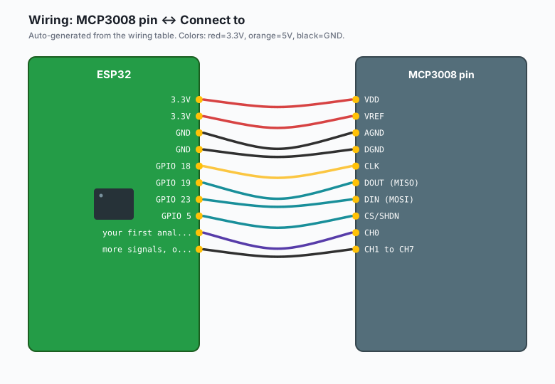
Wiring
| MCP3008 pin | Connect to |
|---|---|
| VDD | 3.3V |
| VREF | 3.3V |
| AGND | GND |
| DGND | GND |
CLK | GPIO 18 |
DOUT (MISO) | GPIO 19 |
DIN (MOSI) | GPIO 23 |
CS/SHDN | GPIO 5 |
| CH0 | your first analog signal |
| CH1 to CH7 | more signals, or GND through 10K if unused |
Tie every unused channel to GND through a 10K resistor. A floating input can bleed charge through the internal multiplexer and show up as ghost readings on the channel you are actually using.
GPIO 18, 19, and 23 are the ESP32’s default hardware SPI pins and GPIO 5 is the default chip select, so the sketch below needs no pin remapping. Avoid GPIO 0, 2, 12, and 15 for CS: those are boot-strapping pins and a pull-up or signal on them at reset can stop the board booting (the boot pins tutorial covers which ones to avoid).
Install
Arduino IDE >> Sketch >> Include Library >> Manage Libraries >> search “MCP3008” >> install Adafruit MCP3008. That is the only dependency; the SPI peripheral ships with the core.
Why the MCP3008 and not the ADS1115
The site has an ADS1115 tutorial, and the two chips answer different questions. The ADS1115 gives you 16 bits over I2C but only 4 channels and a top speed around 860 samples per second. The MCP3008 gives you 10 bits over SPI, 8 channels, and roughly 75 thousand samples per second at 3.3V. Rule of thumb: precision (a load cell, a slow bridge signal) goes to the ADS1115, quantity and speed (eight pots, a bank of LDRs, a fast changing voltage) goes to the MCP3008. If you need both, they share the bus happily since one speaks I2C and the other SPI.
The code
#include <SPI.h>
#include <Adafruit_MCP3008.h>

Adafruit_MCP3008 adc;

const int CS_PIN  = 5;
const float VREF_MV = 3300.0;   // must match what the 3.3V rail measures

void setup() {
  Serial.begin(115200);
  if (!adc.begin(CS_PIN)) {
    Serial.println("MCP3008 begin() failed, check wiring");
    while (1) delay(1000);
  }
}

void loop() {
  for (int ch = 0; ch < 8; ch++) {
    uint32_t sum = 0;
    for (int i = 0; i < 16; i++) {
      sum += adc.readADC(ch);
    }
    float raw = sum / 16.0;
    float mv  = raw * (VREF_MV / 1023.0);

    Serial.printf("CH%d  raw %5.1f  %6.1f mV\n", ch, raw, mv);
  }
  Serial.println("---");
  delay(1000);
}
The 16-sample average is not decoration. The MCP3008 is a fast, successive-approximation converter with no internal averaging, so the last digit flickers on any real signal. Sixteen samples take well under a millisecond and settle it. If you need faster scanning, drop the average to 4 or 1; the chip itself can run far quicker than this loop asks it to.
Note the VREF_MV constant: measure your board’s 3.3V rail once with a
multimeter and put the real number in. Rails run 3.25 to 3.35V, which
is a 1.5% error if you assume 3300 exactly (e.g. a rail that measures
3.28 V turns 1000 mV into a reading of 1009 mV).
What you learned
- SPI buys you 8 analog inputs for 4 GPIO pins, and none of them care whether Wi-Fi is running, because they are not on the ESP32’s ADC at all.
- Powering the ADC at 3.3V makes its logic levels and full-scale range match the ESP32 exactly. The 5V in Arduino diagrams is someone else’s problem, and copying it here costs you a damaged input.
- Sixteen-sample averaging removes converter flicker for free, and one measured constant (the actual rail voltage) removes the biggest systematic error.
When something breaks
- Every channel reads 0: CS is not actually toggling. Check the CS wire goes to GPIO 5 and not the adjacent pin, and that the breadboard row under the chip is making contact.
- Readings jump between two values that never change: you are reading a floating channel. Tie unused channels to GND through 10K and see if the ghosts disappear.
- The chip got hot: VDD and VREF got swapped with AGND in a breadboard shuffle, or 5V reached the board. Power off, check with the multimeter, replace the chip if it took the hit (they are $4, that is why we buy two).
- Values look fine until Wi-Fi connects, then CH0 goes weird: the sensor is on an ADC2 pin of the ESP32 as well as the MCP3008, or the SPI wires run next to the antenna. Keep the SPI bus short and away from the antenna end of the board.
- Top of the pot range never reaches 1023: the signal’s top is below VREF, which is correct behavior. If you need the full 1023 counts for a smaller signal, that is a job for the ADS1115’s gain (the differential tutorial on this site does exactly that).
What to build next
- The ESP32 NTC thermistor tutorial on this site reads temperature with a resistor divider; that divider plugs straight into CH0 and now it can sit far from the board.
- The ESP32 ADS1115 external ADC tutorial is the I2C, 16-bit route when you need resolution more than channel count.
- Pair the eight channels with MQTT publishing (the ESP32 MQTT tutorial covers it) and every pot and probe lands on a dashboard as its own topic.
- The ADC basics tutorial explains the built-in ADC’s quirks, which is the problem this chip solves.
The book IoT with ESP32 bundles the sensor tutorials including this one.