ESP32: read battery voltage and fuel gauge (MAX17048) instead of guessing
Read real state-of-charge from a LiPo with the MAX17048 fuel gauge over I2C. Percent, voltage, and charge rate instead of a voltage lookup table.
Every battery-powered ESP32 project I built before this one guessed. I read the battery voltage with the ADC, divided by a calibration constant, and mapped it to a percentage with a lookup table I found in a forum. It failed in exactly the way everyone’s fails: 100% for a long time, then a cliff, then “20%” that was really zero. A lithium discharge curve is flat. Voltage is a terrible proxy for state of charge, and the lookup table is where that lie gets published.
The MAX17048 is a fuel gauge chip that fixes this properly. It runs a real state-of-charge model (the ModelGauge algorithm, which combines voltage and a coulomb counter) and answers “what percent is left” over I2C in two bytes. It costs about $2 on a breakout.
The trap I hit: I read the percentage once at boot, after the chip had been sitting on the shelf with no battery connected, and my project reported 0% forever. The MAX17048 needs a first real battery connection to learn its baseline. If the battery arrives after the chip has been sitting unpowered, give it a couple of minutes to settle before you trust the number.
What you need
Needed
- ESP32 dev board (e.g. a Feather-style board that already breaks out I2C, about $8)
- MAX17048 breakout module (about $2; the Adafruit one is labeled MAX17048 and has the battery JST header on board)
- A single-cell LiPo battery, 3.7 V, with a JST-PH connector or the leads to crimp one on
- Jumper wires, female-to-female
Nice to have
- Soldering iron + solder, only if your battery leads need a JST connector crimped or soldered on
- Wire stripper for prepping those leads
- Soldering mat and iron stand
- Multimeter to cross-check the voltage reading (the gauge and your meter should agree within about 20 mV)
- Anti-static wristband for handling the breakout
- A USB power meter inline so you can watch charge current for real (e.g. a $10 inline power profiler)
Wiring
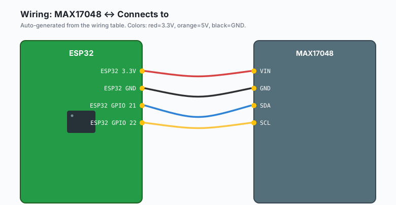
I2C on the ESP32: SDA is GPIO 21, SCL is GPIO 22 by default.
| MAX17048 | Connects to |
|---|---|
VIN | ESP32 3.3V |
GND | ESP32 GND |
SDA | ESP32 GPIO 21 |
SCL | ESP32 GPIO 22 |
| BAT (cell +) | Battery positive wire |
GND (cell -) | Battery negative wire |
The battery powers your project through its own path (e.g. the TP4056 tutorial’s charge board or a Feather’s built-in regulator). The MAX17048 does not pass battery power to the ESP32. It listens to the cell and reports. Keep the load path and the sensing path separate in your head and the wiring stays simple.
Do not set a raw LiPo down with both leads touching metal. A dead shorted LiPo is a fire. Tape the leads until the moment you screw them down.
Install
Arduino IDE >> Sketch >> Include Library >> Manage Libraries, search “MAX1704X”, install the Adafruit MAX1704X library (it covers the MAX17048 and its siblings).
The code
#include <Wire.h>
#include <Adafruit_MAX1704X.h>

Adafruit_MAX17048 gauge;

unsigned long lastPrint = 0;

void setup() {
  Serial.begin(115200);

  if (!gauge.begin()) {
    Serial.println("MAX17048 not found. Check wiring, I2C addr 0x36.");
    while (true) delay(1000);
  }
  Serial.print("Chip version: ");
  Serial.println(gauge.getVersion(), HEX);

  // A chip that just met its battery needs a moment to settle.
  delay(2000);
}

void loop() {
  if (millis() - lastPrint >= 2000) {
    lastPrint = millis();

    float cellV      = gauge.cellVoltage();   // volts
    float cellPct    = gauge.cellPercent();   // 0-100
    float chargeRate = gauge.chargeRate();    // %/hour, negative = discharging

    Serial.printf("V: %.3f  SOC: %.1f%%  rate: %+.2f %%/h\n",
                  cellV, cellPct, chargeRate);
  }
}
Open the serial monitor and let the battery carry the load alone for a few minutes. You should see the percentage sit still while the voltage drops a little, then both move together as the cell empties. That flat voltage with steady percent is the whole reason the chip exists.
What each number is for:
- cellPercent is the headline. This is what you show the user and what you use to decide when to sleep or shut down.
- cellVoltage is the sanity check. If the percentage and the voltage disagree wildly (e.g. 80% at 3.5 V, which is not plausible), the model needs a reset (see troubleshooting).
- chargeRate tells you charging from discharging without any wiring to the charge controller. A solar node knows whether it is winning or losing the day.
What you learned
- Voltage is a bad proxy for state of charge on lithium cells. The discharge curve is flat exactly where you live.
- The MAX17048 runs a real gauge model and reports percent, voltage, and rate over I2C at address 0x36.
- The sensing path and the power path are separate. The gauge listens; it does not feed the ESP32.
- The chip needs one real battery connection to learn its baseline. Numbers right after first contact are not to be trusted.
When something breaks
- 0% forever. The chip reset with the battery disconnected and
never learned the cell. Reconnect the battery while powered, wait a
few minutes, and re-read. If it persists, call
gauge.restart()(a soft reset of the model, not a wipe of your code). - Percentage jumps around. You are reading it while the load pulses (e.g. a Wi-Fi burst every few seconds drags the cell down for 200 ms). Read less often, or average a few reads, or trust the gauge’s own filtering over minutes.
- I2C scan finds nothing at 0x36. SDA and SCL are swapped, or the breakout VIN is fed 5 V into a 3.3 V-only variant. Check the wiring table above before suspecting the chip.
- Numbers disagree with your multimeter. Measure at the BAT pin, not the JST header on the far side of a switch or protection circuit. A protection IC between the cell and the gauge drops tens of millivolts under load.
What to build next
This is the missing piece for the 18650 + TP4056 tutorial: add the gauge and that power board becomes a battery node that knows when to stop trying. Combine it with the deep sleep tutorial and the node sleeps at 10%, wakes, publishes one MQTT message, and goes back to sleep (the fuel gauge keeps its model across deep sleep because the state lives in the chip, powered by the cell itself).
If you are powering from solar, pair it with the solar battery
tutorial: chargeRate() is how you log whether the panel is keeping
up, and the ntfy notifications tutorial is how you get told when it
stops.