ESP32: read an MPU6050 accelerometer and gyroscope over I2C
Wire an MPU6050 to an ESP32 and read acceleration and rotation rate in three axes. The sensor you need for robots, drones, and motion tracking.
The MPU6050 is the IMU (inertial measurement unit) I reach for when I need to know how something is moving or rotating. It has a 3-axis accelerometer (gravity and motion) and a 3-axis gyroscope (rotation rate), all on one chip over I2C. It is the sensor at the heart of most robotics projects, drones, motion controllers, and self-balancing contraptions.
This tutorial covers the wiring, the library, reading raw acceleration and rotation, and the orientation-from-gravity trick that lets you detect tilt without any math you did not write yourself.
What you need
- ESP32 dev board
- MPU6050 breakout board (the GY-521 is the most common; $2 from anywhere)
- 4 jumper wires
Wiring (I2C)
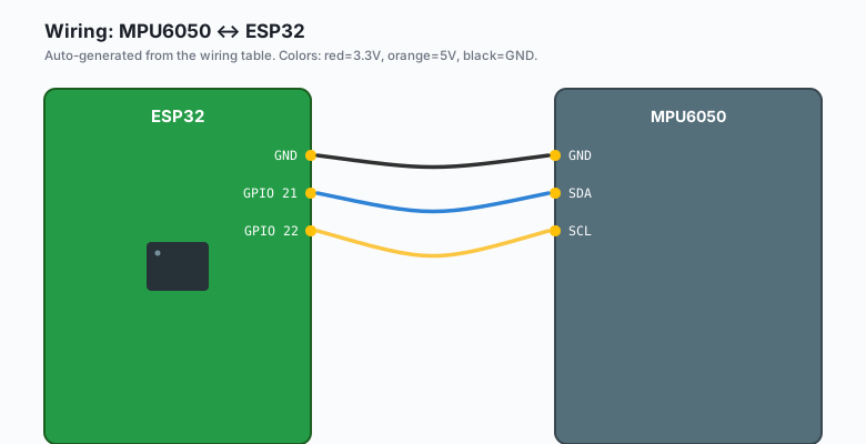
The MPU6050 uses I2C. Same pins as the BME280:
MPU6050 VCC -- ESP32 5V (the GY-521 has a 3.3V regulator onboard)
MPU6050 GND -- ESP32 GND
MPU6050 SDA -- ESP32 GPIO 21
MPU6050 SCL -- ESP32 GPIO 22
The GY-521 breakout has a 3.3V regulator on it. You can power it from 3.3V or 5V; either works. Most projects use 5V because it is easier to find.
If your MPU6050 has an AD0 pin, it controls the I2C address. AD0 to GND = 0x68 (default). AD0 to VCC = 0x69. The library defaults to 0x68.
Install libraries
Sketch >> Include Library >> Manage Libraries >> search for
Adafruit MPU6050. Install it. Also install Adafruit Unified Sensor
and Adafruit BusIO when prompted.
The code
ESP32 (Arduino)
#include <Wire.h>
#include <Adafruit_MPU6050.h>
#include <Adafruit_Sensor.h>

Adafruit_MPU6050 mpu;

void setup() {
  Serial.begin(115200);
  delay(1000);
  Wire.begin();
  if (!mpu.begin()) {
    Serial.println("Could not find MPU6050");
    while (1);
  }
  mpu.setAccelerometerRange(MPU6050_RANGE_2_G);
  mpu.setGyroRange(MPU6050_RANGE_250_DEG);
  mpu.setFilterBandwidth(MPU6050_BAND_21_HZ);
}

void loop() {
  sensors_event_t a, g, temp;
  mpu.getEvent(&a, &g, &temp);
  Serial.print("Accel X: ");
  Serial.print(a.acceleration.x);
  Serial.print("  Y: ");
  Serial.print(a.acceleration.y);
  Serial.print("  Z: ");
  Serial.print(a.acceleration.z);
  Serial.print("  |  Gyro X: ");
  Serial.print(g.gyro.x);
  Serial.print("  Y: ");
  Serial.print(g.gyro.y);
  Serial.print("  Z: ");
  Serial.print(g.gyro.z);
  Serial.println();
  delay(100);
}
Arduino (Uno, Nano, Mega)
#include <Wire.h>
#include <Adafruit_MPU6050.h>
#include <Adafruit_Sensor.h>

Adafruit_MPU6050 mpu;

void setup() {
  Serial.begin(9600);
  delay(1000);
  Wire.begin();
  if (!mpu.begin()) {
    Serial.println("Could not find MPU6050");
    while (1);
  }
  mpu.setAccelerometerRange(MPU6050_RANGE_2_G);
  mpu.setGyroRange(MPU6050_RANGE_250_DEG);
  mpu.setFilterBandwidth(MPU6050_BAND_21_HZ);
}

void loop() {
  sensors_event_t a, g, temp;
  mpu.getEvent(&a, &g, &temp);
  Serial.print("Accel X: ");
  Serial.print(a.acceleration.x);
  Serial.print("  Y: ");
  Serial.print(a.acceleration.y);
  Serial.print("  Z: ");
  Serial.print(a.acceleration.z);
  Serial.print("  |  Gyro X: ");
  Serial.print(g.gyro.x);
  Serial.print("  Y: ");
  Serial.print(g.gyro.y);
  Serial.print("  Z: ");
  Serial.print(g.gyro.z);
  Serial.println();
  delay(100);
}
The MPU6050 library allocates about 700 bytes of RAM for the sensor struct. The Uno’s 2KB is tight; use
F()macro on your Serial prints to save another 100-200 bytes.
MicroPython (ESP32 or Pico)
from machine import I2C, Pin
import time

# ESP32 default I2C: GPIO 21 (SDA), 22 (SCL)
# Pico default I2C: GPIO 0 (SDA), 1 (SCL)
i2c = I2C(0, scl=Pin(22), sda=Pin(21), freq=400_000)
devices = i2c.scan()
print(f'I2C devices: {[hex(d) for d in devices]}')

MPU6050_ADDR = 0x68

# Wake up the MPU6050 (it starts in sleep mode)
i2c.writeto_mem(MPU6050_ADDR, 0x6B, b'\x00')
time.sleep_ms(100)

def read_word(reg):
    data = i2c.readfrom_mem(MPU6050_ADDR, reg, 2)
    v = (data[0] << 8) | data[1]
    return v - 65536 if v >= 32768 else v

while True:
    ax = read_word(0x3B) / 16384.0 * 9.81   # m/s^2
    ay = read_word(0x3D) / 16384.0 * 9.81
    az = read_word(0x3F) / 16384.0 * 9.81
    gx = read_word(0x43) / 131.0 * 0.01745   # rad/s
    gy = read_word(0x45) / 131.0 * 0.01745
    gz = read_word(0x47) / 131.0 * 0.01745
    print(f'Ax: {ax:+.2f} Ay: {ay:+.2f} Az: {az:+.2f}  Gx: {gx:+.2f} Gy: {gy:+.2f} Gz: {gz:+.2f}')
    time.sleep(0.1)
For MicroPython projects with sensor fusion (the complementary filter
or Madgwick), install imu.py from
https://github.com/micropython-IMU/micropython-imu.
Raspberry Pi Python
import smbus2
import time

bus = smbus2.SMBus(1)
MPU6050_ADDR = 0x68

bus.write_byte_data(MPU6050_ADDR, 0x6B, 0)   # wake up
time.sleep(0.1)

def read_word(reg):
    high = bus.read_byte_data(MPU6050_ADDR, reg)
    low = bus.read_byte_data(MPU6050_ADDR, reg + 1)
    v = (high << 8) + low
    return v - 65536 if v >= 32768 else v

while True:
    ax = read_word(0x3B) / 16384.0 * 9.81
    ay = read_word(0x3D) / 16384.0 * 9.81
    az = read_word(0x3F) / 16384.0 * 9.81
    print(f'Ax: {ax:+.2f} Ay: {ay:+.2f} Az: {az:+.2f}')
    time.sleep(0.1)
What you should see
Upload. Open Serial Monitor at 115200 baud. Move the sensor around. You should see the acceleration values change in m/s^2 and the gyroscope values change in rad/s.
When the sensor is sitting still on a flat surface:
- Accel Z reads about +9.8 (gravity)
- Accel X and Y read close to 0
- Gyro X, Y, Z read close to 0
When you tilt the sensor, the accel values redistribute. When you spin it, the gyro values spike.
The two output units
The library gives you two units to choose from:
a.acceleration.xin m/s^2 (what the code above uses)mpu.getAccelerationX()in g (1g = 9.8 m/s^2)
I prefer m/s^2 because it works with the standard gravity constant. For projects that care about “how many g’s of force am I seeing”, use the getter variant.
Detecting tilt from accelerometer only
Without any math you did not write, the accelerometer tells you the sensor’s orientation relative to gravity. The trick:
void loop() {
  sensors_event_t a, g, temp;
  mpu.getEvent(&a, &g, &temp);

  // pitch and roll from gravity vector
  float pitch = atan2(-a.acceleration.x, sqrt(a.acceleration.y * a.acceleration.y +
                                                a.acceleration.z * a.acceleration.z)) * 180.0 / PI;
  float roll  = atan2(a.acceleration.y, a.acceleration.z) * 180.0 / PI;

  Serial.print("Pitch: ");
  Serial.print(pitch);
  Serial.print(" deg  Roll: ");
  Serial.print(roll);
  Serial.println(" deg");
  delay(100);
}
Tilt the sensor forward: pitch changes. Tilt right: roll changes. This is the orientation read that most projects need.
The accelerometer-based tilt is accurate when the sensor is not accelerating. If the sensor is moving, the accel values include both gravity and motion. For tilt during movement, you need a sensor fusion algorithm (complementary filter, Kalman filter). The book ESP32 Robotics Projects covers the complementary filter in depth.
Reading rotation rate (the gyro)
The gyroscope measures rotation rate, not angle. To get total rotation angle, integrate:
unsigned long lastUpdate = 0;
float yawAngle = 0;

void loop() {
  sensors_event_t a, g, temp;
  mpu.getEvent(&a, &g, &temp);

  unsigned long now = millis();
  float dt = (now - lastUpdate) / 1000.0;
  lastUpdate = now;

  // gyro Z is the rotation around the Z axis (yaw)
  yawAngle += g.gyro.z * dt;   // rad/s * s = rad

  Serial.print("Yaw: ");
  Serial.print(yawAngle * 180.0 / PI);
  Serial.println(" deg");
  delay(50);
}
The result is yaw angle in degrees. The longer you run, the more the angle drifts (gyro drift is a real thing). For projects that need accurate rotation tracking, fuse the gyro with the accelerometer using a complementary filter.
The I2C address trick
The default address is 0x68. If you want two MPU6050s on one I2C bus (rare but possible for stereo motion tracking), set the AD0 pin on the second one to VCC and use address 0x69:
Adafruit_MPU6050 mpu1;   // 0x68
Adafruit_MPU6050 mpu2;   // 0x69

void setup() {
  Wire.begin();
  mpu1.begin();
  mpu2.begin(0x69);
}
For more than two MPU6050s, you need an I2C multiplexer (TCA9548A).
Range settings
The MPU6050 supports multiple ranges:
mpu.setAccelerometerRange(MPU6050_RANGE_2_G);   // +/- 2g (default)
mpu.setAccelerometerRange(MPU6050_RANGE_4_G);   // +/- 4g
mpu.setAccelerometerRange(MPU6050_RANGE_8_G);   // +/- 8g
mpu.setAccelerometerRange(MPU6050_RANGE_16_G);  // +/- 16g

mpu.setGyroRange(MPU6050_RANGE_250_DEG);   // +/- 250 deg/s
mpu.setGyroRange(MPU6050_RANGE_500_DEG);   // +/- 500 deg/s
mpu.setGyroRange(MPU6050_RANGE_1000_DEG);  // +/- 1000 deg/s
mpu.setGyroRange(MPU6050_RANGE_2000_DEG);  // +/- 2000 deg/s
Smaller range = more precision. Larger range = handles more violent motion. For a self-balancing robot, +/- 2g accel and +/- 500 deg/s gyro is fine. For a drone or a crash-prone project, +/- 16g and +/- 2000 deg/s.
Filter bandwidth
The MPU6050 has a built-in low-pass filter. Setting the bandwidth filters out high-frequency noise (vibration, electrical interference):
mpu.setFilterBandwidth(MPU6050_BAND_21_HZ); // defaultOptions: 21, 44, 94, 184, 260 Hz. Lower = more filtering but slower response. For most projects, 21 or 44 Hz is right. For a high-speed robot, 94 or 184 Hz.
What you learned
- MPU6050 reads 3-axis acceleration (m/s^2) and 3-axis rotation (rad/s) over I2C.
- Wiring is 4 wires. The breakout board has a 3.3V regulator so 5V or 3.3V both work.
- Tilt (pitch and roll) can be derived from the accelerometer alone when the sensor is stationary.
- Gyro integration gives you rotation angle, but it drifts. Fuse with accel for accurate orientation.
When something breaks
- “Could not find MPU6050”. Wrong address (try 0x69), wrong wiring, bad solder joint on the breakout.
- Readings are noisy. Filter bandwidth too high. Set to 21 Hz.
- Tilt reads correctly when stationary, wrong when moving. You are using accel-only orientation. Need sensor fusion.
- Gyro drifts over time. That is the MPU6050; it is not broken. Use sensor fusion to correct.
What to build next
- The HC-SR04 ultrasonic tutorial is the other sensor most robots use (distance sensing). Combine with MPU6050 for obstacle-avoiding robots.
- The ESP32 servo tutorial uses MPU6050 as feedback: a camera gimbal that stays level as the base moves.
- The book ESP32 Robotics Projects covers sensor fusion (complementary filter, Madgwick, Mahony) in depth.