ESP32: read a DS18B20 temperature sensor with OneWire
Wire one or many DS18B20 temperature sensors to a single ESP32 GPIO pin. Multiple sensors, one wire, accurate to 0.5 C.
The DS18B20 is the temperature sensor I default to when I want multiple sensors on one wire, or when I need accuracy better than ±0.5 C, or when the sensor is more than a meter away from the microcontroller. It uses Dallas Semiconductor’s OneWire protocol, which lets you put dozens of sensors on a single GPIO pin and read each one individually.
This tutorial covers the wiring, the library setup, reading one sensor, and reading multiple sensors on one pin.
What you need
- ESP32 dev board
- One or more DS18B20 sensors (the bare TO-92 package, or the waterproof stainless steel probe version)
- 4.7k ohm resistor (for the pull-up)
- Jumper wires
The waterproof DS18B20 probe comes pre-wired with red (VCC), black (GND), and yellow (data). It is about $3 and is what I use for any project where the sensor is more than a few centimeters from the board.
Wiring
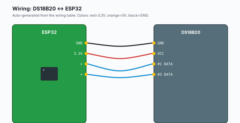
DS18B20 GND -- ESP32 GND
DS18B20 DATA -- ESP32 GPIO 4 --[ 4.7k pull-up ]-- ESP32 3.3V
DS18B20 VCC -- ESP32 3.3V
The pull-up resistor is mandatory. Without it, the OneWire bus does not work. The data line floats when no sensor is driving it, and the protocol relies on the pull-up to hold the line HIGH between transactions.
For multiple DS18B20s on one pin, just connect all the data lines to the same GPIO pin. Each DS18B20 has a unique 64-bit address burned into it during manufacturing. The library uses the address to talk to each sensor individually.
DS18B20 #1 DATA ---+
DS18B20 #2 DATA ---+--- ESP32 GPIO 4 --[ 4.7k pull-up ]-- ESP32 3.3V
DS18B20 #3 DATA ---+
You can put dozens of sensors on one pin. The bus is address-based, not position-based, so order does not matter.
Install libraries
Sketch >> Include Library >> Manage Libraries >> search for
OneWire by Paul Stoffregen. Install it. Also install DallasTemperature
by Miles Burton.
The code
ESP32 (Arduino)
#include <OneWire.h>
#include <DallasTemperature.h>

#define ONE_WIRE_PIN 4

OneWire oneWire(ONE_WIRE_PIN);
DallasTemperature sensors(&oneWire);

void setup() {
  Serial.begin(115200);
  delay(1000);
  sensors.begin();
}

void loop() {
  sensors.requestTemperatures();
  float tempC = sensors.getTempCByIndex(0);
  if (tempC == -127.0) {
    Serial.println("Failed to read DS18B20");
  } else {
    Serial.print("Temperature: ");
    Serial.print(tempC);
    Serial.println(" C");
  }
  delay(2000);
}
Arduino (Uno, Nano, Mega)
#include <OneWire.h>
#include <DallasTemperature.h>

#define ONE_WIRE_PIN 2   // any digital pin works; pin 2 is convenient on Uno

OneWire oneWire(ONE_WIRE_PIN);
DallasTemperature sensors(&oneWire);

void setup() {
  Serial.begin(9600);
  delay(1000);
  sensors.begin();
}

void loop() {
  sensors.requestTemperatures();
  float tempC = sensors.getTempCByIndex(0);
  if (tempC == -127.0) {
    Serial.println("Failed to read DS18B20");
  } else {
    Serial.print("Temperature: ");
    Serial.print(tempC);
    Serial.println(" C");
  }
  delay(2000);
}
The Uno has less RAM than the ESP32 (2KB vs 320KB). If you have many sensors (more than 10), drop the resolution to 9 bits to save RAM.
MicroPython (ESP32 or Pico)
from machine import Pin
import onewire
import ds18x20
import time

# ESP32: any GPIO; pin 4 is safe
# Pico: any GPIO; pin 4 is safe
ow = onewire.OneWire(Pin(4))
sensors = ds18x20.DS18X20(ow)

roms = sensors.scan()
print(f'Found {len(roms)} sensor(s)')

while True:
    sensors.convert_temp()
    time.sleep_ms(750)   # 12-bit resolution conversion time
    for rom in roms:
        temp = sensors.read_temp(rom)
        print(f'Sensor {rom.hex()}: {temp:.2f} C')
    time.sleep(2)
Raspberry Pi Python (with kernel OneWire driver)
The Pi has a built-in OneWire driver that exposes DS18B20 sensors through sysfs. Enable it once:
sudo raspi-config >> Interface Options >> 1-Wire >> EnableThen in Python:
import glob
import time

# The kernel driver creates /sys/bus/w1/devices/28-*/w1_slave entries
# for each DS18B20 found. 28- is the family code.
base = '/sys/bus/w1/devices/'
sensors = sorted(glob.glob(base + '28-*'))
print(f'Found {len(sensors)} sensor(s)')

def read(path):
    with open(path + '/w1_slave') as f:
        lines = f.readlines()
    if lines[0].strip()[-3:] != 'YES':
        return None
    t_pos = lines[1].find('t=')
    if t_pos == -1:
        return None
    return int(lines[1][t_pos+2:]) / 1000.0

while True:
    for s in sensors:
        print(f'{s.split("/")[-1]}: {read(s)} C')
    time.sleep(2)
This pattern works for both bare DS18B20 sensors and the waterproof probe, on any Raspberry Pi with the kernel driver enabled.
What you should see
Upload. Open Serial Monitor at 115200 baud. You should see:
Temperature: 23.31 C
Temperature: 23.31 C
Temperature: 23.30 C
If every read returns -127.00, the wiring is wrong. Check the pull-up
resistor first.
Reading multiple sensors by index
The getTempCByIndex(0) reads the first sensor. getTempCByIndex(1) reads
the second. For a small number of sensors (under 10), this works:
void loop() {
  sensors.requestTemperatures();
  Serial.print("Sensor 0: ");
  Serial.print(sensors.getTempCByIndex(0));
  Serial.print(" C  Sensor 1: ");
  Serial.print(sensors.getTempCByIndex(1));
  Serial.print(" C  Sensor 2: ");
  Serial.print(sensors.getTempCByIndex(2));
  Serial.println(" C");
  delay(2000);
}
The order of indices depends on the order the sensors respond on the bus. It can change if you add or remove sensors. For stable addressing, use the address-based read below.
Reading multiple sensors by address
First, find the addresses:
void setup() {
  Serial.begin(115200);
  delay(1000);
  sensors.begin();

  int count = sensors.getDeviceCount();
  Serial.print("Found ");
  Serial.print(count);
  Serial.println(" sensors.");

  for (int i = 0; i < count; i++) {
    DeviceAddress addr;
    sensors.getAddress(addr, i);
    Serial.print("Sensor ");
    Serial.print(i);
    Serial.print(": ");
    for (int j = 0; j < 8; j++) {
      if (addr[j] < 16) Serial.print("0");
      Serial.print(addr[j], HEX);
    }
    Serial.println();
  }
}
Run this once, copy the addresses from the Serial Monitor, then write the addresses as constants:
DeviceAddress livingRoom = {0x28, 0xFF, 0x64, 0x1E, 0xC2, 0x00, 0x00, 0x9A};
DeviceAddress kitchen    = {0x28, 0xFF, 0x57, 0x32, 0xC2, 0x00, 0x00, 0x4D};

void loop() {
  sensors.requestTemperatures();
  Serial.print("Living room: ");
  Serial.print(sensors.getTempC(livingRoom));
  Serial.print(" C  Kitchen: ");
  Serial.print(sensors.getTempC(kitchen));
  Serial.println(" C");
  delay(2000);
}
Address-based reads do not depend on bus order. You can add or remove sensors without breaking the others.
The “device count is 0” bug
The most common DS18B20 problem is that sensors.getDeviceCount() returns
0. This means the library cannot find any sensor on the bus.
Causes:
- Pull-up resistor missing or wrong value (4.7k is the standard pick).
- Wiring reversed on VCC and GND. The DS18B20 has them swapped compared to many sensors; check the pinout.
- Data line is on GPIO 0, GPIO 2, or another boot pin. Use GPIO 4 or another general-purpose pin.
- 5V power on a 3.3V DS18B20 (some variants are 5V-tolerant; check the datasheet for your specific part).
The parasitic power mode
There is a variant of DS18B20 wiring called “parasitic power” where the sensor draws its power from the data line instead of a separate VCC wire. Wire it like this:
DS18B20 GND -- ESP32 GND
DS18B20 DATA -- ESP32 GPIO 4 --[ 4.7k pull-up ]-- ESP32 3.3V
DS18B20 VCC -- ESP32 GND   (yes, VCC and GND both go to GND)
In code:
sensors.setWaitForConversion(false);Parasitic power saves one wire. It is finicky for long wire runs (the parasitic capacitance gets too high) but works fine for under 3 m. For anything longer, use the normal wiring.
Resolution and conversion time
The DS18B20 supports 9-bit to 12-bit resolution. Higher resolution = more accurate but slower.
sensors.setResolution(12);   // 0.0625 C, 750 ms conversion time
sensors.setResolution(9);    // 0.5 C, 94 ms conversion time
For a slow-changing indoor temperature sensor, 12-bit is fine. For a fast-moving sensor (e.g. measuring water flow), 9 or 10-bit gives you faster readings at the cost of resolution.
What you learned
- DS18B20 uses OneWire: one data wire for one or many sensors.
- Each sensor has a unique 64-bit address. The library uses addresses to identify each sensor.
- The 4.7k pull-up resistor is mandatory.
- 0.5 C accuracy, 0.0625 C resolution, range -55 to 125 C.
When something breaks
- Every read returns -127. Pull-up missing, wrong value, or wiring reversed. The -127 is the library’s “no response” code.
- First read works, second fails. Power issue. Add a capacitor across VCC and GND at the sensor (10-100 uF).
- Readings are off by a few degrees. You have a counterfeit sensor. Yes, this happens. The genuine DS18B20 has a recognizable ROM signature; fakes do not. Buy from a reputable source.
- Bus gets stuck after a few hours. Add
sensors.setWaitForConversion(true)and ensure the conversion time is appropriate for your resolution.
What to build next
- The BME280 tutorial reads temperature, humidity, and pressure in one chip. Compare to DS18B20 for indoor use.
- The deep sleep tutorial uses DS18B20 as a wake source: only wake the ESP32 every 5 minutes to read and publish.
- The book ESP32 in Production covers long-wire runs (up to 100 m on twisted pair), multiple buses, and proper grounding for industrial deployments.