ESP32: GPIO basics, digital read, digital write, and the pull-up trick
How to read and write the ESP32's GPIO pins, when to use the internal pull-ups, and the input-only pins that catch everyone once.
GPIO is the part of the ESP32 you spend 90% of your time on. Read a button, light an LED, drive a relay, talk to a sensor. All GPIO. Get this foundation right and every project gets easier. Get it wrong and you spend a Saturday debugging a floating pin that is reading random noise.
This tutorial covers the basics: digital write (output), digital read (input), the internal pull-up trick that lets you wire a button with no resistors, and the four pins that are input-only and cannot do output.
What you need
- An ESP32 dev board
- An LED and a 220 ohm resistor (any color)
- A momentary pushbutton (the four-leg tactile kind)
- Three jumper wires
- The toolchain install from the previous tutorial
The GPIO map you need to memorize
The ESP32 has 34 GPIO pins, but not all of them are usable for general work.
| GPIO range | Notes |
|---|---|
GPIO 0 | Boot pin. Avoid unless you know why. |
GPIO 1, 3 | Used for serial debug. Avoid. |
GPIO 2 | Boot pin, often has the onboard LED. |
GPIO 4-5 | General purpose. Safe. |
GPIO 6-11 | Connected to internal flash. Never use these. |
GPIO 12-15 | Boot pins. General purpose is OK if you are careful about boot state. |
GPIO 16-33 | General purpose. Safe. |
GPIO 34, 35, 36, 39 | Input only. Cannot drive output. |
GPIO 37, 38 | Not exposed on most dev boards. |
The pins that say “Never use these” (GPIO 6-11) are physically connected to the ESP32’s flash chip. Using them as GPIO crashes the program.
The pins that are input-only (GPIO 34-39, minus 37-38 which are not
exposed) cannot be set as outputs. The IDE silently ignores pinMode()
on them if you ask for OUTPUT. The fix is to pick a different pin.
The exact safe-pin list depends on your board. Most dev boards expose GPIO 4, 5, 13, 14, 16, 17, 18, 19, 21, 22, 23, 25, 26, 27, 32, 33. Use one of those for first projects. You will avoid every weird boot mode and every input-only trap.
Wiring
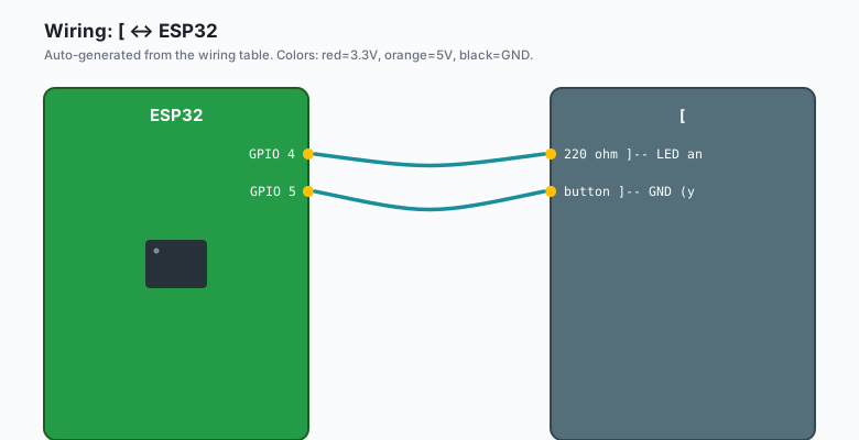
The blink circuit:
ESP32 GPIO 4  --[ 220 ohm ]-- LED anode (long leg) -- LED cathode (short leg) -- GND
ESP32 GPIO 5  --[ button ]-- GND  (yes, just one wire + the button)
That is the entire circuit. The button needs no resistor because of the internal pull-up (covered below).
The code: output
const int LED_PIN = 4;

void setup() {
  pinMode(LED_PIN, OUTPUT);
}

void loop() {
  digitalWrite(LED_PIN, HIGH);
  delay(500);
  digitalWrite(LED_PIN, LOW);
  delay(500);
}
Upload. The LED blinks at 1 Hz. HIGH is 3.3V, LOW is 0V. The 220 ohm
resistor limits current to about 10 mA, which is bright enough for most
LEDs and well within the ESP32’s per-pin spec.
The current limit per GPIO is 40 mA absolute max, 20 mA recommended. Going over 20 mA for sustained periods damages the pin over time.
The code: input with internal pull-up
const int LED_PIN = 4;
const int BTN_PIN = 5;

void setup() {
  pinMode(LED_PIN, OUTPUT);
  pinMode(BTN_PIN, INPUT_PULLUP);   // <-- the magic
}

void loop() {
  if (digitalRead(BTN_PIN) == LOW) {
    digitalWrite(LED_PIN, HIGH);
  } else {
    digitalWrite(LED_PIN, LOW);
  }
}
Upload. Press the button. The LED lights up. Release. The LED goes off.
The trick is INPUT_PULLUP. It enables the ESP32’s internal pull-up
resistor (about 45k ohms) on GPIO 5. This holds the pin HIGH when the
button is not pressed. When you press the button, the pin connects to
GND through the switch contacts, pulling it LOW.
Read that again. Pressed = LOW. Released = HIGH. This is the opposite of what feels natural. Most button tutorials on Arduino use the same convention for the same reason: it lets you skip the external resistor.
The reason pinMode(BTN_PIN, INPUT_PULLUP) works:
- No external resistor needed. Saves wiring.
- The pin cannot float (always reads HIGH or LOW, never random noise).
- Pressed-vs-released is unambiguous.
The reason pinMode(BTN_PIN, INPUT) (no pull-up) does not work:
- The pin is floating when the button is not pressed.
- Reads random noise. Your code sees “pressed” when you did not press.
- This is the bug that causes 80% of “my button does not work” complaints.
Always use INPUT_PULLUP for buttons unless you have a specific reason
not to. Same applies to limit switches, reed switches, and most other
momentary-contact inputs.
The code: debounce
The next bug you will hit is button bounce. The button makes and breaks contact a few times before settling. Your code sees multiple presses for one physical press. The fix is software debouncing.
The pattern I use in every project:
const int LED_PIN = 4;
const int BTN_PIN = 5;

enum ButtonState { IDLE, PRESSED, RELEASED };
ButtonState state = IDLE;
unsigned long lastChange = 0;
const unsigned long DEBOUNCE_MS = 30;

void setup() {
  pinMode(LED_PIN, OUTPUT);
  pinMode(BTN_PIN, INPUT_PULLUP);
}

void loop() {
  bool reading = digitalRead(BTN_PIN) == LOW;

  switch (state) {
    case IDLE:
      if (reading) {
        state = PRESSED;
        lastChange = millis();
      }
      break;
    case PRESSED:
      if (millis() - lastChange > DEBOUNCE_MS) {
        if (reading) {
          // confirmed press
          digitalWrite(LED_PIN, !digitalRead(LED_PIN));   // toggle
          state = RELEASED;
        } else {
          state = IDLE;
        }
      }
      break;
    case RELEASED:
      if (!reading) {
        state = IDLE;
        lastChange = millis();
      }
      break;
  }
}
Press the button. The LED toggles. Press it again. The LED toggles back. One press, one toggle, no bounce.
The pattern is a state machine. Three states:
- IDLE: waiting for a press. When we see
LOW, move to PRESSED. - PRESSED: waiting 30 ms for the bounce to settle. After that, if still LOW, it was a real press. Otherwise it was noise.
- RELEASED: waiting for the button to be released before we accept another press.
30 ms is enough for most buttons. Cheaper buttons and membrane switches might need 50-100 ms.
Reading from input-only pins (GPIO 34-39)
If you need an analog sensor or a button on GPIO 34, the code is the
same except you cannot drive them as output. pinMode(34, INPUT_PULLUP)
works for reading.
void setup() {
  pinMode(34, INPUT);   // GPIO 34 has no internal pull-up
  // no INPUT_PULLUP option for input-only pins
}

void loop() {
  int v = digitalRead(34);
  // ...
}
GPIO 34-39 do not have internal pull-ups. If you wire a button to one of these, you need an external 10k pull-up resistor. Most of the time, just use GPIO 4 or another general-purpose pin instead.
What you learned
- The ESP32 has 34 GPIO pins, but 6 of them (6-11) are off-limits, 4 (34-39 minus 37-38) are input-only, and 5 (0, 1, 2, 3, 12-15) have boot-mode caveats.
digitalWrite(pin, HIGH)sets a pin to 3.3V.LOWis 0V.INPUT_PULLUPenables the internal pull-up resistor so you can wire a button with no external resistor.- Buttons need software debounce to work reliably. The state-machine pattern above is the simplest version that actually works.
When something breaks
- Button reads as pressed when nothing is pressed. No pull-up. Add
INPUT_PULLUPor wire an external 10k resistor. - Button reads as pressed every 2-3 presses. Debounce is too short for your button. Try 50 or 100 ms.
- LED does not light. Check the wiring polarity. The LED’s longer leg is the anode; that side goes to the GPIO side, not to GND.
- Code does not compile. You used a GPIO number that does not exist (e.g. GPIO 37, 38 on a board that does not expose them). Check the silkscreen.
What to build next
- The button debounce tutorial goes deeper on the state-machine pattern and shows you how to handle long-press vs short-press.
- The analog ADC tutorial reads a potentiometer or analog sensor, which is the other half of GPIO (analog, not just digital).
- The deep sleep tutorial uses wake-on-button as a way to save battery on projects that only need to run when you press something.