ESP32: read temperature with a $1 NTC thermistor (Steinhart-Hart done simply)
Turn a $1 NTC thermistor and a 10K resistor into an ESP32 temperature sensor: divider math, analogReadMilliVolts to dodge ADC nonlinearity, and the beta equation.
An NTC thermistor is a resistor that gets less resistive as it gets warmer. That is the whole sensor. Pair it with a fixed 10K resistor, read the voltage in the middle, and you have a temperature sensor for a dollar that survives water, dust, and being stepped on (things that retire a BME280 in one afternoon). I use them for anything that does not need laboratory accuracy: the garage, the compost pile, the 3D printer enclosure, the fridge.
The trap: my first version read the raw ADC count, mapped 0 to 4095
onto 0 to 3.3V linearly, and called it done. The numbers moved in the
right direction, so it looked finished, and the garage sensor sat
persistently 4 to 5 degrees off for a month before I checked it against
a thermometer. The ESP32’s ADC is just not linear across its range,
especially at the ends. The fix is one function: analogReadMilliVolts()
applies the factory calibration stored in the chip and returns actual
millivolts. Same hardware, one function change, and the error dropped
to under a degree.
What you need
Needed
| Item | Qty | Purpose | Est. cost |
|---|---|---|---|
| ESP32 dev board (ESP32-DevKitC or clone) | 1 | the brain | $8-$15 |
| 10K NTC thermistor, B = 3950 (e.g. MF52 or MF58 bead type) | 1 | the temperature sensor | $1 |
| 10K resistor, 1% | 1 | the fixed half of the divider | $0.10 |
| Breadboard | 1 | connecting it up | $3 |
| Jumper wires | 3 | divider to ESP32 | $1 |
Two details worth the extra cents. Get the 1% resistor, not 5%: the fixed resistor’s value goes into the math directly, so its error is your error, permanently. And check the thermistor’s datasheet for the B value (3950 is the common one, 3435 shows up too); a wrong B value is the number one cause of “works but reads odd”.
Nice to have
- Multimeter to sanity-check the divider voltage against the printed millivolts
- Soldering iron and solder if you are attaching longer leads to the thermistor for a remote location
- Soldering iron stand and helping hands for that lead job
- Anti-static wristband when handling the bare board
- Magnifying goggles for reading resistor bands (1% brown-black- orange vs the 5% gold band misread)
- Soldering mat to keep the bench clean
- Wire stripper for the thermistor leads
Wiring
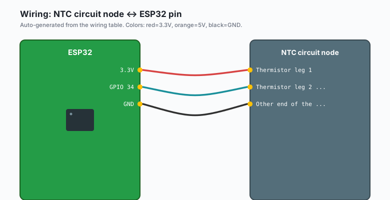
| NTC circuit node | ESP32 pin |
|---|---|
| Thermistor leg 1 | 3.3V |
| Thermistor leg 2 + one end of the 10K | GPIO 34 |
| Other end of the 10K | GND |
This orientation (thermistor on the 3.3V side, fixed resistor on the GND side) means warmer temperatures push the divider voltage up. Swap the two parts and the readings invert direction; the code below has a one-line change for that case, but pick one and be consistent.
Use an ADC1 pin: GPIO 32 to GPIO 39. GPIO 34 to 39 are input-only, which is fine here, but note they have no internal pull-ups, so the external 10K does real work. ADC2 pins stop working once Wi-Fi is on, which the ADC basics tutorial covers in full.
The math, done simply
The honest equation for an NTC is the Steinhart-Hart equation, a cubic in 1/T with three coefficients you fit from a datasheet table. The simplified version nearly every hobby project actually uses is the beta equation:
1/T = 1/T0 + (1/B) * ln(R/R0)T0 is 298.15 K (25 degrees C), R0 is the resistance at 25 C (10K here), and B is the material constant from the datasheet (3950 here). For a typical 10K NTC between 0 and 70 C, the beta version stays within about half a degree of the full equation, which is better than the rest of your parts anyway. If you later need real accuracy, measure the thermistor at three temperatures (e.g. ice water, room, boiling) and fit the three Steinhart-Hart coefficients yourself. Start with beta; most projects never need the cubic.
The code
#include <math.h>

const int   NTC_PIN    = 34;
const float SERIES_R   = 10000.0;  // the fixed resistor, measured if you can
const float R0         = 10000.0;  // thermistor resistance at 25 C
const float B          = 3950.0;   // from the thermistor's datasheet
const float T0         = 298.15;   // 25 C in kelvin
const float VCC_MV     = 3300.0;   // measure your 3.3V rail once

void setup() {
  Serial.begin(115200);
  analogReadResolution(12);
  analogSetAttenuation(ADC_11db);   // full 0-3.3V window
}

void loop() {
  uint32_t sum_mv = 0;
  const int n = 32;
  for (int i = 0; i < n; i++) {
    sum_mv += analogReadMilliVolts(NTC_PIN);
    delay(2);
  }
  float mv = sum_mv / (float)n;

  // Thermistor on the 3.3V side, fixed resistor on the GND side:
  //   ratio = SERIES_R / (SERIES_R + R_ntc)  so  R_ntc = SERIES_R * (1-ratio)/ratio
  float ratio = mv / VCC_MV;
  float r_ntc = SERIES_R * (1.0 - ratio) / ratio;

  // Beta equation: 1/T = 1/T0 + (1/B) ln(R/R0)
  float temp_c = 1.0 / (1.0 / T0 + log(r_ntc / R0) / B) - 273.15;

  Serial.printf("millivolts %.1f  R_ntc %.0f  temp %.2f C\n",
                mv, r_ntc, temp_c);
  delay(1000);
}
If you wired the thermistor to GND and the fixed resistor to 3.3V,
change the resistance line to r_ntc = SERIES_R * ratio / (1.0 - ratio).
Everything downstream stays the same.
The 32-sample average costs about 64 ms and is what makes the printed value sit still. A single ADC read on a divider this high-impedance wobbles in the last digit.
Calibrate it once, cheaply
You do not need a reference thermometer to fix a small constant offset.
Two glasses of water and a thermometer you trust: ice water should
read 0 C, and tap-hot water compared against a cooking thermometer tells
you the rest. If the sensor reads a consistent 3 degrees high, subtract
3 in code and be done. A constant offset is the failure mode of a wrong
or imprecise resistor; a reading that is only right in the middle of
the range is the failure mode of raw ADC counts, which you already
fixed with analogReadMilliVolts().
What you learned
- An NTC plus one fixed resistor is a complete temperature sensor, and the beta equation converts resistance to temperature in one line.
analogReadMilliVolts()reads the chip’s factory calibration and skips the raw-counts-to-volts guesswork that cost me a month of accuracy.- Averaging many short reads settles a high-impedance divider, and one measured constant (the real 3.3V rail) beats a labeled one.
When something breaks
- Reads a constant nonsense temperature around -273 or a math error: the ratio is out of range, which means the pin reads near 0 or near 3.3V. A leg came off, or you are on a pin with no divider connected.
- Temperature moves the wrong way when you warm it: the divider is oriented opposite to the code. Use the alternate resistance line above (or swap the parts on the breadboard).
- Off by a fixed few degrees: wrong B value, or a 5% fixed resistor, or the 3.3V rail is not really 3.3V. Measure the rail, check the datasheet, and if a constant offset remains, calibrate it out as above.
- Readings go wild once Wi-Fi starts: you are on an ADC2 pin. Move the divider to GPIO 32 to 39 (ADC1) and it survives Wi-Fi.
- Cable longer than a meter, readings drift: voltage drop and pickup on long analog runs. Put an MCP3008 (the SPI ADC tutorial on this site) near the sensor and send SPI instead of analog.
What to build next
- The ESP32 DS18B20 tutorial is the calibration-free alternative: a digital temperature sensor with the math already done inside.
- The BME280 tutorial adds humidity and pressure if the project is weather-shaped rather than temperature-shaped.
- Hang the thermistor off an MCP3008 channel (the SPI ADC tutorial on this site) when the sensor lives more than a meter from the board.
- Log the readings with the InfluxDB timeseries tutorial and the garage finally gets a temperature graph.
The book IoT with ESP32 bundles the sensor tutorials including this one.