ESP32: drive a MAX7219 8-digit 7-segment display
Wire a MAX7219 to an ESP32 to drive an 8-digit 7-segment display over SPI. The right pick for showing sensor numbers, counters, or clocks.
The MAX7219 is the chip that drives every “8-digit 7-segment display module” you see on Amazon. The breakout has the chip, the 8 digits, and the current-limiting resistors all in one board. It speaks SPI, which means 3 wires from the ESP32, and you can chain multiple displays by daisy-chaining the DOUT of one to the DIN of the next.
I use these for counters, clocks, temperature displays, anything that needs to show a number from across the room. The OLED is better for graphs and text; the MAX7219 is better for big readable digits.
What you need
- ESP32 dev board (or Arduino, Pico, Pi)
- MAX7219 8-digit 7-segment display module (the common one with 5-pin header: VCC, GND, DIN, CS, CLK; about $3-5)
- 5 jumper wires
Buy the “common cathode” version, which is the standard MAX7219 module. The “TM1637” 4-digit displays look similar but use a different (and less capable) chip; that one is its own tutorial.
Wiring
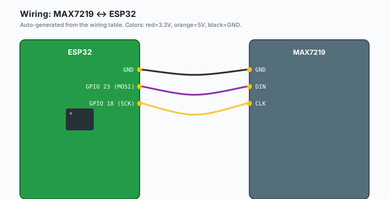
The MAX7219 uses SPI. The default SPI pins on the ESP32 are GPIO 18 (SCK), 19 (MISO, not used here), and 23 (MOSI, which becomes DIN on the display).
MAX7219 VCC -- ESP32 5V  (the module is 5V; logic is 3.3V-tolerant)
MAX7219 GND -- ESP32 GND
MAX7219 DIN -- ESP32 GPIO 23  (MOSI)
MAX7219 CS  -- ESP32 GPIO 5   (chip select, also called LOAD)
MAX7219 CLK -- ESP32 GPIO 18  (SCK)
The MAX7219 is a 5V chip, but its logic inputs are 3.3V-tolerant. The 5V VCC powers the LEDs; the 3.3V signals from the ESP32 drive the chip correctly.
The module has an
ISETresistor on the back (usually labeled R1). It sets the LED current. The default is 10kohm, which is fine for indoor use. For outdoor or high-brightness, replace it with a smaller value (see “Brightness” below).
Install libraries
Sketch >> Include Library >> Manage Libraries >> search
LedControl (by Eberhard Fahle). Install it. This is the standard
library for MAX7219 with Arduino.
The code
ESP32 (Arduino)
#include <LedControl.h>

// DIN, CLK, CS, number of daisy-chained modules
LedControl lc = LedControl(23, 18, 5, 1);

void setup() {
  lc.shutdown(0, false);     // wake up the display
  lc.setIntensity(0, 8);     // brightness 0-15
  lc.clearDisplay(0);
}

void loop() {
  // Show a counter from 0 to 99999999
  for (long i = 0; i <= 99999999; i++) {
    lc.setNumber(0, i, false);   // false = no leading zeros
    delay(50);
    if (i >= 12345) break;       // stop early for the demo
  }

  // Show a static temperature
  lc.clearDisplay(0);
  lc.setChar(0, 7, 'C', false);   // 'C' on the rightmost digit
  lc.setNumber(0, 234, false);    // "234" on the left
  delay(2000);

  // Show a message (limited to 8 chars)
  lc.clearDisplay(0);
  lc.setRow(0, 0, 0x7E);   // 'b'
  lc.setRow(0, 1, 0x30);   // 'r'
  lc.setRow(0, 2, 0x79);   // 'E'
  lc.setRow(0, 3, 0x7C);   // 'd'
  delay(2000);
}
Arduino (Uno, Nano, Mega)
Same code, but the default SPI pins are 11 (MOSI) and 13 (SCK). The LedControl library lets you set them explicitly:
#include <LedControl.h>

// For Uno/Nano: DIN=11, CLK=13, CS=10
LedControl lc = LedControl(11, 13, 10, 1);

void setup() {
  lc.shutdown(0, false);
  lc.setIntensity(0, 8);
  lc.clearDisplay(0);
}

void loop() {
  lc.setNumber(0, 12345, false);
  delay(1000);
  lc.clearDisplay(0);
  delay(1000);
}
The 5V Arduino drives the MAX7219’s logic at 5V, which is exactly what it wants. No level shifting needed.
MicroPython (ESP32 or Pico)
from machine import Pin, SPI
import time

# ESP32: SCK=18, MOSI=23; CS=5
# Pico: SCK=2, MOSI=3; CS=5
spi = SPI(0, sck=Pin(18), mosi=Pin(23), baudrate=10_000_000)
cs = Pin(5, Pin.OUT)

cs.value(1)

def send(cmd, data):
    cs.value(0)
    spi.write(bytes([cmd, data]))
    cs.value(1)

def init_display():
    send(0x0C, 0x01)   # shutdown register: normal operation
    send(0x0F, 0x00)   # display test: off
    send(0x0B, 0x07)   # scan limit: all 8 digits
    send(0x0A, 0x08)   # intensity: 8/16
    send(0x09, 0x00)   # decode mode: no decode (we use raw segments)

def clear():
    for d in range(1, 9):
        send(d, 0x00)

def show_number(n):
    """Show a number, right-aligned, up to 8 digits."""
    s = f"{n:08d}"
    for d, ch in enumerate(s):
        digit = int(ch)
        # digit patterns 0-9 (no decode mode)
        patterns = [0x7E, 0x30, 0x6D, 0x79, 0x33, 0x5B, 0x5F, 0x70, 0x7F, 0x7B]
        send(d + 1, patterns[digit])

init_display()
clear()
print("MAX7219 ready")

n = 0
while True:
    show_number(n)
    n = (n + 1) % 100000000
    time.sleep(0.1)
The MicroPython version is verbose because there is no LedControl library port. The patterns array is the 7-segment encoding for digits 0-9; the same encoding the MAX7219’s “decode mode” would do in hardware. Without decode mode, the ESP32 sends raw segment bytes.
Raspberry Pi Python
import spidev
import time

spi = spidev.SpiDev()
spi.open(0, 0)
spi.max_speed_hz = 10_000_000

def send(cmd, data):
    spi.xfer2([cmd, data])

def init_display():
    send(0x0C, 0x01)
    send(0x0F, 0x00)
    send(0x0B, 0x07)
    send(0x0A, 0x08)
    send(0x09, 0x00)

def clear():
    for d in range(1, 9):
        send(d, 0x00)

def show_number(n):
    s = f"{n:08d}"
    patterns = [0x7E, 0x30, 0x6D, 0x79, 0x33, 0x5B, 0x5F, 0x70, 0x7F, 0x7B]
    for d, ch in enumerate(s):
        send(d + 1, patterns[int(ch)])

init_display()
clear()

n = 0
while True:
    show_number(n)
    n = (n + 1) % 100000000
    time.sleep(0.1)
Enable SPI on the Pi: sudo raspi-config >> Interface Options >> SPI
Enable. Then
pip3 install spidev.
What you should see
A counter that increments from 0 to 12345, then shows “234C” (degrees Celsius), then shows “bred” (B-R-E-D in a custom font, this is the demo for raw segment control). Each message holds for 2 seconds.
If you see only one digit, the scan limit register is wrong. Set it
to 7 (8 digits) using send(0x0B, 0x07).
Daisy-chaining multiple modules
The MAX7219 has a DOUT pin. Wire it to the DIN of the next module. Both share the same CLK and CS lines. The LedControl library takes the count of daisy-chained modules as the 4th argument:
LedControl lc = LedControl(23, 18, 5, 4); // 4 daisy-chained modulesTo write to module index 2 (the 3rd in the chain):
lc.setNumber(2, 42, false); // show 42 on the 3rd moduleThe MAX7219 supports up to 8 modules per chain. That is 64 digits, which is enough for most clocks and large counters.
Brightness
The setIntensity value (0-15) controls brightness. The hardware
limit is set by the ISET resistor:
- 10 kohm (default): max current ~40 mA per segment
- 5 kohm: ~80 mA per segment (bright but hot)
- 20 kohm: ~20 mA per segment (dim, good for battery projects)
For an outdoor clock, swap to 5 kohm and run at intensity 12-15. For indoor, leave the resistor alone and use intensity 4-8 (lower is better for the eyes at night).
Showing negative numbers and decimals
setNumber does not show negative numbers. To show “-40” (a freezer
alarm), use the raw segment byte for the minus sign (0x01) and write
it directly to a specific digit:
lc.setRow(0, 0, 0x01);    // minus sign on the leftmost digit
lc.setDigit(0, 1, 4, false);
lc.setDigit(0, 2, 0, false);
For decimals, write the digit and the decimal point (0x80) to the same row:
lc.setDigit(0, 5, 2, true);   // '2.' on digit 5 (decimal point on)
lc.setDigit(0, 6, 7, false);  // '7' on digit 6
What you learned
- MAX7219 is the standard chip for 8-digit 7-segment displays.
- 3 wires for SPI (DIN, CLK, CS). Daisy-chain up to 8 modules.
- The LedControl library handles all the register-level work.
- Brightness is software-controllable (intensity 0-15) and hardware- settable (the ISET resistor).
When something breaks
- Display is completely dark.
shutdown(0, false)not called, or wrong VCC (must be 5V, not 3.3V). - All segments light up. Display test mode is on. Send
0x0F, 0x00to disable. - Garbled digits. SPI clock too high. Drop to 1 MHz:
SPI.beginTransaction(SPISettings(1000000, MSBFIRST, SPI_MODE0)). - One digit works, the rest are blank.
scan limitregister is set too low. Set to 7 for all 8 digits. - Display flickers when Wi-Fi is active. Add a 10uF capacitor across VCC/GND at the module. The 5V rail can sag during Wi-Fi bursts.
What to build next
- The shift register tutorial is the lower-level way to drive a 7-segment without a driver chip. More wiring, more code, more learning.
- The OLED tutorial is the better pick when you need to show text, not numbers.
- The book ESP32 Smart Home has a 4-digit clock with NTP time sync built from this pattern.