ESP32: add 16 GPIO pins with the MCP23017 I2C port expander
Run out of GPIO on your ESP32? The MCP23017 adds 16 GPIO pins over I2C using only 2 wires. Multi-platform code for ESP32, Arduino, Pico, and Pi.
The MCP23017 is the part I reach for when an ESP32 project runs out of GPIO. It gives you 16 more GPIO pins over I2C, using only 2 of the ESP32’s own pins (SDA and SCL). The whole chip is in a DIP package that fits on a breadboard, costs about $2, and works on 3.3V or 5V.
The pattern I use most: an ESP32 with a BME280, an OLED, and a 4-relay board. That fills the I2C bus and uses maybe 8 GPIO pins. Add an MCP23017 and I have 16 more GPIOs for buttons, LEDs, or relay expansion, without giving up any of the originals.
What you need
- ESP32 dev board (or Arduino Uno/Nano, or Pico, or Pi)
- MCP23017 chip (the DIP-28 package on a breakout board is the easiest to breadboard; about $2)
- 2x 4.7kohm pull-up resistors for SDA and SCL (most breakout boards include them, but check)
- Breadboard and jumper wires
The MCP23017 is one of two common Microchip port expanders. The other is the MCP23008 (8 pins). The ‘017 is the more useful one because you can chain up to 8 of them on the same I2C bus for 128 GPIOs total.
Wiring
The MCP23017 uses I2C. Same two wires as every other I2C device.
MCP23017 VDD  -- ESP32 3.3V
MCP23017 VSS  -- ESP32 GND
MCP23017 SDA  -- ESP32 GPIO 21
MCP23017 SCL  -- ESP32 GPIO 22
MCP23017 A0   -- ESP32 GND  (I2C address 0x20; see table)
MCP23017 A1   -- ESP32 GND
MCP23017 A2   -- ESP32 GND
MCP23017 RESET -- ESP32 3.3V (tie high; the chip resets if it floats)
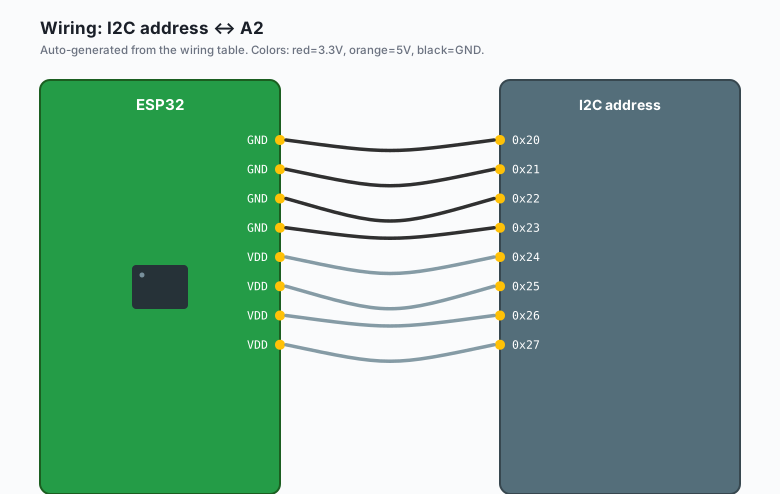
The A0/A1/A2 pins set the I2C address. Tie them to GND or VDD to pick one of 8 addresses:
A2 | A1 | A0 | I2C address |
|---|---|---|---|
GND | GND | GND | 0x20 |
GND | GND | VDD | 0x21 |
GND | VDD | GND | 0x22 |
GND | VDD | VDD | 0x23 |
| VDD | GND | GND | 0x24 |
| VDD | GND | VDD | 0x25 |
| VDD | VDD | GND | 0x26 |
| VDD | VDD | VDD | 0x27 |
That is how you put 8 MCP23017 chips on the same bus. The book version of this build (4 relay boards, 4 sensor arrays, 16 LEDs) uses 3 expanders on addresses 0x20, 0x21, 0x22.
Install libraries
Sketch >> Include Library >> Manage Libraries >> search
Adafruit MCP23017 Arduino Library. Install it.
The code
ESP32 (Arduino)
#include <Wire.h>
#include <Adafruit_MCP23X17.h>

Adafruit_MCP23X17 mcp;

void setup() {
  Serial.begin(115200);
  Wire.begin();
  mcp.begin(0x20);   // address from the A0/A1/A2 table

  // Pins 0-7 as outputs, pins 8-15 as inputs with pull-ups
  for (int i = 0; i < 8; i++) {
    mcp.pinMode(i, OUTPUT);
  }
  for (int i = 8; i < 16; i++) {
    mcp.pinMode(i, INPUT_PULLUP);
  }
}

void loop() {
  // Blink the first 4 outputs
  for (int i = 0; i < 4; i++) {
    mcp.digitalWrite(i, HIGH);
  }
  delay(500);
  for (int i = 0; i < 4; i++) {
    mcp.digitalWrite(i, LOW);
  }
  delay(500);

  // Read the 8 input pins and print them as a byte
  uint8_t inputs = 0;
  for (int i = 0; i < 8; i++) {
    if (mcp.digitalRead(i + 8)) {
      inputs |= (1 << i);
    }
  }
  Serial.print("Inputs: 0x");
  Serial.println(inputs, HEX);
}
Arduino (Uno, Nano, Mega)
The code is identical. Wire.begin() picks the right I2C pins per
board (A4/A5 on the Uno, GPIO 21/22 on the ESP32).
#include <Wire.h>
#include <Adafruit_MCP23X17.h>

Adafruit_MCP23X17 mcp;

void setup() {
  Serial.begin(9600);
  Wire.begin();
  mcp.begin(0x20);

  for (int i = 0; i < 16; i++) {
    mcp.pinMode(i, OUTPUT);
  }
}

void loop() {
  for (int i = 0; i < 16; i++) {
    mcp.digitalWrite(i, HIGH);
  }
  delay(500);
  for (int i = 0; i < 16; i++) {
    mcp.digitalWrite(i, LOW);
  }
  delay(500);
}
The MCP23017 is 5V tolerant on its I2C lines even when powered from 3.3V. The Adafruit library uses the Wire library, which on a 5V Arduino pulls SDA/SCL to 5V. On the ESP32 (3.3V) this is fine, but if you mix 5V and 3.3V devices on the same I2C bus, use a level shifter.
MicroPython (ESP32 or Pico)
from machine import I2C, Pin
import time

# ESP32: GPIO 21 (SDA), 22 (SCL)
# Pico: GPIO 0 (SDA), 1 (SCL)
i2c = I2C(0, scl=Pin(22), sda=Pin(21), freq=400_000)

MCP_ADDR = 0x20

# IODIR register: 1 = input, 0 = output
# IODIRA = 0x00, IODIRB = 0x01
i2c.writeto_mem(MCP_ADDR, 0x00, b'\x00')   # GPA all outputs
i2c.writeto_mem(MCP_ADDR, 0x01, b'\xff')   # GPB all inputs (with pull-ups)

# GPPU register: enable pull-ups on GPB
i2c.writeto_mem(MCP_ADDR, 0x0D, b'\xff')

print("MCP23017 ready at 0x{:02x}".format(MCP_ADDR))

while True:
    i2c.writeto_mem(MCP_ADDR, 0x12, b'\x0f')   # OLATA = 0b00001111
    time.sleep(0.5)
    i2c.writeto_mem(MCP_ADDR, 0x12, b'\x00')   # OLATA = 0
    time.sleep(0.5)

    # Read GPB (input port)
    inb = i2c.readfrom_mem(MCP_ADDR, 0x13, 1)[0]
    print("Inputs: 0x{:02x}".format(inb))
The MCP23017 register map: 0x12 = OLATA (output latch A), 0x13 = GPIOA (read input A), 0x14 = OLATB, 0x15 = GPIOB. The library handles all of this; the bare-register version above is for when you cannot install a library (e.g. on a constrained Pico build).
Raspberry Pi Python
import smbus2
import time

bus = smbus2.SMBus(1)
MCP_ADDR = 0x20

# IODIRA = 0x00, all outputs
bus.write_byte_data(MCP_ADDR, 0x00, 0x00)
# IODIRB = 0x01, all inputs
bus.write_byte_data(MCP_ADDR, 0x01, 0xFF)
# GPPUA = 0x0C, pull-ups on port A
bus.write_byte_data(MCP_ADDR, 0x0C, 0xFF)

print("MCP23017 ready")

while True:
    bus.write_byte_data(MCP_ADDR, 0x12, 0x0F)
    time.sleep(0.5)
    bus.write_byte_data(MCP_ADDR, 0x12, 0x00)
    time.sleep(0.5)
Enable I2C on the Pi first: sudo raspi-config >> Interface Options
I2C >> Enable. Then
pip3 install smbus2if not already installed.
What you should see
Open the Serial Monitor at 115200 baud. The first 4 outputs (GPA0
through GPA3) blink on and off every 500 ms. The 8 input pins (GPB0
through GPB7) print their state as a hex byte every cycle. Wire a
jumper from GPB0 to GND, the byte changes to 0xFE (bit 0 cleared).
Pull it to 3.3V, it goes back to 0xFF.
I2C speed
The MCP23017 supports I2C at 100 kHz (standard), 400 kHz (fast), and 1.7 MHz (high-speed). The ESP32’s default Wire library is 100 kHz; the MCP23017 is faster than most I2C devices. For a project with 16 fast inputs (e.g. a 16-channel button matrix), bump the clock:
Wire.setClock(400000);For 16 buttons polled at 100 Hz, the faster clock cuts the I/O time from 1.6 ms to 0.4 ms per scan. Matters when you are doing real-time work; does not matter for indicator LEDs.
Interrupts (the INT pin)
The MCP23017 has an INT pin that goes LOW when an input pin changes state (if you enable it). That is the right way to do “wait for button press” without polling the bus in a tight loop.
mcp.setupInterrupts(true, false, LOW);   // mirror, open-drain, active-low
mcp.enableInterruptPin(8, CHANGE);        // pin 8, fire on either edge
attachInterrupt(digitalPinToInterrupt(15), buttonISR, FALLING);

void buttonISR() {
  uint8_t port = mcp.getCapturedInterrupt();
  Serial.print("Interrupt on pin: ");
  Serial.println(port);
}
The getCapturedInterrupt() returns the port value at the moment of
the interrupt. This is the pattern for low-power projects where the
ESP32 sleeps until a button is pressed. The MCP23017 holds the INT pin
LOW while the ESP32 is asleep; the ESP32 wakes, reads the captured
value, and goes back to sleep.
What you learned
- The MCP23017 adds 16 GPIOs over I2C using only 2 pins.
- A0/A1/A2 set the address. 8 chips per bus = 128 GPIOs.
- The Adafruit library handles all the register math.
- The INT pin is the way to do low-power button inputs.
When something breaks
- I2C scanner does not find 0x20. Check A0/A1/A2 wiring (they must be tied, not floating). Check RESET is tied to VDD, not floating. A floating reset will sometimes work, sometimes not.
- Outputs toggle but inputs read 0xFF always. Pull-ups are not enabled. Set the GPPU register (0x0C / 0x0D) to 0xFF for inputs.
- Inputs read random values. Long wires. Add 100nF capacitor across VDD/VSS at the chip. The MCP23017 is sensitive to noise on the supply.
- Bus errors after a few hours. I2C bus is locked up. Add a
Wire.reset()or a hardware watchdog (the TP-Link “I2C bus reset” trick: pulse SCL 9 times manually).
What to build next
- The shift register tutorial is the other way to expand outputs. Use that when you do not need inputs.
- The relay module tutorial combined with this gives you 16 switched outputs from 2 ESP32 pins.
- The book ESP32 Smart Home has a 64-output lighting controller built from 4 MCP23017 chips.