ESP32: drive a 74HC595 shift register for 8 extra output pins
Add 8 output pins to your ESP32 using only 3 GPIO pins and a 74HC595 shift register. For LEDs, relay arrays, and 7-segment without a driver.
The 74HC595 is the chip that has been on hobbyist projects since before the Arduino existed. It is a serial-in, parallel-out shift register. You push 8 bits in one at a time over 3 wires, then latch them to 8 output pins. The output pins hold their state until you push a new byte.
The trade vs. the MCP23017: the 74HC595 is outputs only, and you cannot read back the state. For 8 LEDs, 8 relays, or a 7-segment display, that is fine. For 16 buttons, you want the MCP23017.
I use 74HC595s when I need a handful of LEDs or relays and do not want to spend the money on a port expander. About 30 cents per chip.
What you need
- ESP32 dev board (or Arduino Uno/Nano)
- 74HC595 shift register chip (DIP-16 package, about 30 cents)
- 8 LEDs + 8 220 ohm resistors, or 8 relays on a driver board, or one 7-segment display
- 0.1uF decoupling capacitor
- Breadboard, jumper wires
The 74HC595 is the through-hole, 5V-tolerant version. The 74HC595N (DIP package) is the one to breadboard. The 74LV595A is the 3.3V variant; it works but is less common.
Wiring
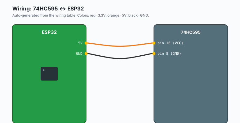
74HC595 pin 16 (VCC)  -- ESP32 5V
74HC595 pin 8  (GND)  -- ESP32 GND
74HC595 pin 10 (SRCLR) -- ESP32 5V    (tie HIGH; shift register clear, active LOW)
74HC595 pin 13 (OE)   -- ESP32 GND    (output enable, tie LOW to enable outputs)
74HC595 pin 14 (SER)  -- ESP32 GPIO 23  (serial data in, MOSI)
74HC595 pin 11 (SRCLK)-- ESP32 GPIO 18  (shift clock, SCK)
74HC595 pin 12 (RCLK) -- ESP32 GPIO 5   (latch clock, chip select)

74HC595 pins 15, 1-7 (QA-QH) -- your 8 LEDs/resistors/relays
0.1uF cap              -- 74HC595 pin 16 to pin 8 (VCC to GND, at the chip)
The decoupling capacitor is mandatory. The 74HC595 switches all 8 outputs at once, and that creates a current spike on the supply. The 0.1uF cap absorbs it. Without it, the chip can glitch or the ESP32 can brown out.
The
SRCLR(shift register clear) andOE(output enable) pins are active LOW. Tie them to VCC and GND respectively unless you need to clear or disable the outputs from a GPIO.
Install libraries
None. The 74HC595 is simple enough that you can drive it with raw SPI, no library needed.
The code
ESP32 (Arduino)
#include <SPI.h>

const int LATCH_PIN = 5;

void setup() {
  SPI.begin();
  pinMode(LATCH_PIN, OUTPUT);
  digitalWrite(LATCH_PIN, LOW);
}

void writeShiftRegister(uint8_t data) {
  digitalWrite(LATCH_PIN, LOW);
  SPI.transfer(data);
  digitalWrite(LATCH_PIN, HIGH);
}

void loop() {
  // Light one LED at a time, walking across all 8
  for (int i = 0; i < 8; i++) {
    writeShiftRegister(1 << i);
    delay(200);
  }
}
The pattern 1 << i is a single bit moving across the byte. When
i = 0, the byte is 0b00000001 (Q0 high). When i = 7, it is
0b10000000 (Q7 high).
Arduino (Uno, Nano, Mega)
#include <SPI.h>

const int LATCH_PIN = 10;   // any digital pin works for CS

void setup() {
  SPI.begin();
  pinMode(LATCH_PIN, OUTPUT);
}

void writeShiftRegister(uint8_t data) {
  digitalWrite(LATCH_PIN, LOW);
  SPI.transfer(data);
  digitalWrite(LATCH_PIN, HIGH);
}

void loop() {
  for (int i = 0; i < 8; i++) {
    writeShiftRegister(1 << i);
    delay(200);
  }
}
Same code; the SPI pins default to 11/12/13 on the Uno, and the CS pin is 10. Both work the same way.
Daisy-chaining
Wire QH’ (pin 9) of the first 74HC595 to SER (pin 14) of the second. Share all other control lines. Now 16 bits become 16 outputs.
void writeShiftRegister16(uint16_t data) {
  digitalWrite(LATCH_PIN, LOW);
  SPI.transfer16(data);   // or two SPI.transfer() calls
  digitalWrite(LATCH_PIN, HIGH);
}
You can chain up to ~8 chips reliably. After that, the SPI clock period exceeds the 74HC595’s setup time and bits start to corrupt. For 8+ outputs, use multiple latch pins or a different driver (the MCP23017, or a chain of TPIC6B595 high-current shift registers).
74HC595 vs. TPIC6B595 for relays
The 74HC595 can only source about 6 mA per output. That is fine for an LED, but a relay coil wants 50-100 mA. The TPIC6B595 is the relay- rated version: open-drain outputs that switch up to 500 mA each, up to 50V. The pinout is identical. Drop-in replacement.
For 8 relay coils, I use the TPIC6B595 with 5V signal relays. The ESP32’s 3.3V is enough to drive the TPIC’s logic inputs; the relay coils run on a separate 5V supply through the TPIC’s drain pins.
7-segment without a driver
The 74HC595 can drive a single 7-segment display. Wire the segment pins (a-g, dp) to QA-QH and write the segment pattern:
const uint8_t SEG_4 = 0b01100110;   // 0x66
const uint8_t SEG_7 = 0b11111000;   // 0xF8 (only a-g; bit 7 is dp, off)

void loop() {
  writeShiftRegister(SEG_4);
  delay(1000);
  writeShiftRegister(SEG_7);
  delay(1000);
}
For a 4-digit display, you need 4 shift registers (one per digit) and a transistor array to multiplex the common anode/cathode. This is the project the MAX7219 was invented to replace. If you need more than one digit, the MAX7219 is the right pick.
Bit order and the SPI quirk
SPI on the ESP32 sends MSB first by default. The 74HC595 expects MSB first too. The first bit you send ends up at QH (pin 7, the last output), the last bit ends up at QA (pin 15, the first output). If you find your LEDs lighting in reverse order, either bit-reverse the byte or send it as 2 nibbles reversed.
To send LSB first (matches the visual order: bit 0 to QA):
SPI.setBitOrder(LSBFIRST);Timing and clock speed
The 74HC595’s max clock is about 25 MHz at 5V. The ESP32’s default
SPI clock is 80 MHz (way too fast) but SPI.transfer() in Arduino
uses the SPI_CLOCK_DIV4 default which is 20 MHz on the ESP32. That
is on the edge; for reliability, slow it down:
SPI.beginTransaction(SPISettings(10'000'000, MSBFIRST, SPI_MODE0));
SPI.transfer(data);
SPI.endTransaction();
10 MHz is safe. 1 MHz is safe even on long wires.
What you learned
- The 74HC595 is 8 outputs from 3 pins, and chains for 16, 24, 32.
- It is outputs only. No read-back.
- 6 mA per pin is fine for LEDs. Use the TPIC6B595 for relays.
- MSB first by default. The first bit sent ends up at the last output pin.
When something breaks
- All 8 LEDs are dim. Missing 0.1uF decoupling cap. Add it across VCC/GND at the chip.
- Outputs are stuck on their initial state. Latch pin not being toggled. The 74HC595 updates its outputs only on the rising edge of the latch.
- Outputs are garbled or stuck high. SPI clock too fast. Drop to 1 MHz.
- ESP32 resets when you write to the shift register. Power supply brownout. The 5V pin on the USB bus is shared with the USB-serial chip; the 8 LEDs can pull enough current to glitch it. Add a 100uF cap on the 5V rail, or use an external 5V supply.
- First LED is always on. SRCLR (pin 10) is not tied HIGH. When SRCLR floats LOW, the chip clears itself.
What to build next
- The MAX7219 tutorial is the right pick when you need 8+ digit displays.
- The MCP23017 tutorial gives you 16 GPIOs that can also be inputs.
- The book ESP32 in Production has a 64-channel LED driver board built from 8 TPIC6B595s.