ESP32: read high temperatures with a K-type thermocouple and MAX6675
Measure up to 600 C with a K-type thermocouple and MAX6675 amplifier on an ESP32. Wiring, the 220ms update gotcha, and when to upgrade to a MAX31855.
My espresso machine runs at 93 C at the group head and my soldering iron claims 350 C at the tip. A DS18B20 tops out at 125 C and a thermistor gets you to maybe 150 C before the numbers stop meaning anything. For anything hotter you need a thermocouple, and the cheapest way to read one is the MAX6675.
The trap I hit: I wired the MAX6675 the way every pinout diagram shows, read it in a loop with no delay, and got a number that never changed. Then I waited a quarter second between reads and it worked. The conversion time is 220 milliseconds. Read it faster and you just re-read the same sample, wondering why your process never heats up.
What you need
Needed
- ESP32 dev board (any WROOM-based board, about $8)
- MAX6675 breakout module with a K-type thermocouple probe included, about $5 (the common blue module on a small PCB)
- Jumper wires, female-to-female work best for this module
- Something actually hot to measure (e.g. a heat gun, a 3D printer nozzle, a mug of just-boiled water for a sanity check)
Nice to have
- Soldering iron + solder (the probe leads often need a crimp or a solder joint at the terminal block)
- Soldering mat and iron stand for that work
- Multimeter with a thermocouple input, so you can cross-check the MAX6675 against a second reading (this caught my first bad probe)
- Anti-static wristband for handling the module
Wiring
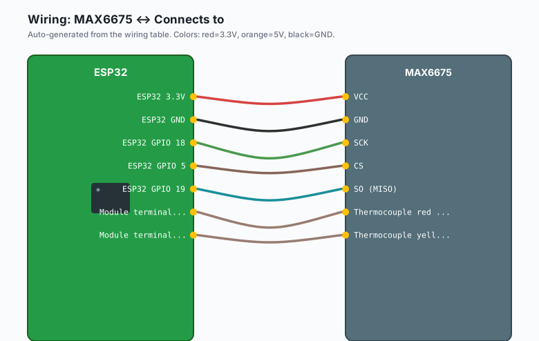
The MAX6675 talks SPI but only listens, so you can share a bus with other SPI devices if you give it its own chip select.
| MAX6675 | Connects to |
|---|---|
VCC | ESP32 3.3V |
GND | ESP32 GND |
SCK | ESP32 GPIO 18 |
CS | ESP32 GPIO 5 |
SO (MISO) | ESP32 GPIO 19 |
| Thermocouple red wire | Module terminal marked + |
| Thermocouple yellow wire | Module terminal marked - |
K-type probes use red as negative and yellow as positive in the US color scheme. That is backwards from every other wire convention I know, and it trips everyone exactly once.
Never run thermocouple wire parallel to power cables. The signal at the probe is microvolts and any induced noise shows up as temperature. If the probe wire must cross a mains cable, cross it at 90 degrees.
Install
Arduino IDE >> Sketch >> Include Library >> Manage Libraries, search “MAX6675”, install the library by Adafruit.
The code
#include <max6675.h>

#define MAX6675_CS   5
#define MAX6675_SCK  18
#define MAX6675_MISO 19

MAX6675 thermocouple(MAX6675_SCK, MAX6675_CS, MAX6675_MISO);

unsigned long lastRead = 0;

void setup() {
  Serial.begin(115200);
  // The MAX6675 needs 220ms after power-up before its first
  // conversion is valid. Do not skip this wait.
  delay(500);
}

void loop() {
  if (millis() - lastRead >= 250) {
    lastRead = millis();
    double celsius = thermocouple.readCelsius();

    if (isnan(celsius)) {
      Serial.println("Probe open circuit or not connected");
    } else {
      Serial.print(celsius, 1);
      Serial.println(" C");
    }
  }
}
That is the whole sensor side. The chip does the cold-junction compensation (it measures the temperature where the probe plugs in and corrects for it) and the ADC conversion internally.
Two details worth knowing:
- The MAX6675 resolves to 0.25 C. The datasheet range stops at +1023.75 C, but the practical ceiling with the cheap modules is about 600 C. Past that the module traces drift.
- A read returns a floating-point NaN when the probe is disconnected. The chip has a real open-thermocouple flag, which is why the code above checks for it instead of trusting the number.
For a logging build, push the reading out over the network (e.g. the MQTT tutorial on this site publishes a reading every 10 seconds and the loop above slots straight into it).
What you learned
- A thermocouple is two dissimilar metals making a voltage you cannot read directly. The amplifier chip is not an accessory, it is the sensor.
- The MAX6675 gives 0.25 C resolution up to about 600 C over three signal wires, with an open-probe flag for free.
- The conversion takes 220 ms. Read slower than that, not faster.
- The red wire on a K-type is negative. Nobody believes this until they check.
When something breaks
- Readings never change. You are polling faster than the 220 ms
conversion time. Space your reads at 250 ms or more (the code above
does this with
millis(), notdelay()). - Reads a steady 25-30 C no matter what. The probe wires are swapped at the terminal block. K-type red is negative, yellow is positive. Swap them and re-read.
- Readings go insane above 100 C. The probe tip is touching metal it should not touch (e.g. the pan wall instead of the pan bottom), or the junction at the terminal block is loose. Check the crimp before you blame the chip.
- NaN on every read. Probe open circuit. Either it is physically disconnected or the thermocouple snapped at the tip (they are thin and they do snap). Keep a spare probe, they are $2.
What to build next
Pair this with the HX711 weight scale tutorial and you have most of a roasting monitor: bean mass and bean temperature on one ESP32, graphed on the sensor dashboard. If you need a wider range or negative temperatures, the MAX31855 breakout is the drop-in upgrade (same three signal wires, 14-bit readings from -200 C up).
The ntfy notifications tutorial is the natural alarm layer: push a phone notification when the reading crosses a threshold, from the same chip.