ESP32: tones and waveforms from the true DAC
Generate real analog tones, ramps, and waveforms on the ESP32's true 8-bit DAC pins (GPIO25/26), from a beep to a sine sweep.
Most “ESP32 audio” tutorials you will find use PWM and a low-pass filter. That works, but the ESP32 has something better hiding on two pins: a true 8-bit DAC on GPIO25 and GPIO26. Real analog voltage out, no filter, no PWM whine. I found this out the annoying way, after building a PWM tone generator for a door chime and then reading the datasheet and finding two DACs staring back at me the whole time.
The trap is that these two pins are easy to kill and impossible to miss once you know: GPIO25 and GPIO26 are also the pins many ESP32 breakouts use for the SD card slot or the PSRAM interface (e.g. on the WROVER-based boards). If your board has those, the DAC pins may be taken. Check before you design around them.
What you need
Needed
- ESP32 dev board with GPIO25/26 exposed (e.g. ESP32-DevKitC, about $8; avoid WROVER modules for this project since their PSRAM uses GPIO16/17 and some boards route SD to 25/26).
- 8 ohm speaker or piezo transducer.
- 1 resistor, 220 ohm (series protection for the speaker).
- 1 capacitor, 10 uF electrolytic (AC coupling, blocks the DC bias).
- Breadboard + 4 jumper wires.
- 3.5mm aux cable or alligator clips, to connect to a speaker or amp.
Nice to have
- Soldering iron + solder, if you attach headers to a bare module.
- Soldering iron stand, for parking the hot iron.
- Helping hands, to hold wires while soldering.
- Anti-static wristband, for bare-module work.
- Magnifying goggles, for reading the tiny pin labels on compact boards.
- Soldering mat, to protect the desk.
- Wire stripper, for clean speaker-wire ends.
Wiring
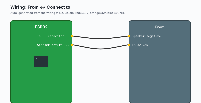
| From | Connect to |
|---|---|
ESP32 GPIO25 (DAC1) | 220 ohm resistor -> speaker positive |
| Speaker negative | 10 uF capacitor + (then cap - to GND) |
ESP32 GND | Speaker return / cap negative |
For a piezo buzzer you can drive GPIO25 straight to the buzzer (piezo draws almost nothing). For an 8 ohm speaker, the 220 ohm resistor in series is not optional; it protects the DAC pin from overcurrent. The 10 uF cap in series with the speaker blocks the DC half of the signal (speakers only care about AC; DC just heats the coil).
GPIO25 ---[220R]---+--- speaker +
                   |
              (10uF cap in series with speaker, + toward GPIO25 side)
                   |
               speaker - --- GND
Only pins GPIO25 (DAC1) and GPIO26 (DAC2) have true DAC output. Any other pin gives you PWM, which is a different technique entirely (see the PWM LEDC tutorial). If your board is a DevKit-V1 clone with unlabeled pins, check the pinout before wiring; some clones mislabel.
Install
No libraries needed for the Arduino framework: the ESP32 Arduino core ships with the DAC API. Just make sure the ESP32 board package is installed (Arduino IDE >> Tools >> Board >> Boards Manager >> search “esp32” >> install).
The code
Beeps and tones (Arduino)
The ESP32 Arduino core v3 has a dacWrite function and a
dacOutputVoltage API. The simplest possible tone is a square wave by
hand:
const int DAC_PIN = 25;   // GPIO25 = DAC1

// Square wave tone: flip between 0V and 3.3V at the note's frequency
void toneRaw(int freqHz, int durationMs) {
  long halfPeriodUs = 500000L / freqHz;
  long cycles = (long)freqHz * durationMs / 1000;
  for (long c = 0; c < cycles; c++) {
    dacWrite(DAC_PIN, 255);        // 3.3V
    delayMicroseconds(halfPeriodUs);
    dacWrite(DAC_PIN, 0);          // 0V
    delayMicroseconds(halfPeriodUs);
  }
}

void setup() {
  Serial.begin(115200);
  delay(1000);
}

void loop() {
  toneRaw(440, 500);   // A4: concert A
  delay(500);
  toneRaw(880, 500);   // A5: the octave above
  delay(2000);
}
This is the “blink an LED but with sound” version, and it sounds like it (harsh, buzzy, with harmonics everywhere). Sometimes that is exactly the right sound for an alarm. For nicer tones you want a sine wave.
Sine wave (the real DAC advantage)
Generate a sine table once, then walk through it at a rate that sets the pitch:
const int DAC_PIN = 25;

// 256-sample sine table, 8-bit DAC values (0-255), centered at 128
uint8_t sineTable[256];
void buildSineTable() {
  for (int i = 0; i < 256; i++) {
    sineTable[i] = (uint8_t)(128.0 + 127.0 * sin(2.0 * PI * i / 256.0));
  }
}

// Play a sine at freqHz using the table (sample rate = freqHz * 256)
void playSine(int freqHz, int durationMs) {
  const int TABLE_SIZE = 256;
  long totalSamples = (long)freqHz * TABLE_SIZE / 1000 * durationMs / 1000;
  // Simpler: compute total samples directly
  totalSamples = (long)freqHz * durationMs / 1000 * TABLE_SIZE;
  int step = 1;
  long idx = 0;
  unsigned long nextSampleUs = micros();
  unsigned long samplePeriodUs = 1000000UL / (freqHz * TABLE_SIZE);
  while (idx < totalSamples) {
    if (micros() >= nextSampleUs) {
      dacWrite(DAC_PIN, sineTable[idx % TABLE_SIZE]);
      idx++;
      nextSampleUs += samplePeriodUs;
    }
  }
}

void setup() {
  Serial.begin(115200);
  buildSineTable();
  delay(1000);
}

void loop() {
  playSine(440, 1000);   // A4 for one second, smooth and clean
  delay(1000);
}
The difference is audible immediately. A square wave at 440 Hz sounds like an old arcade game. The sine at 440 Hz sounds like a tuning fork. Same pitch, very different quality, and the only difference is the waveform you write to the DAC.
Ramps and arbitrary waveforms (the real flexibility)
The DAC does not care what numbers you send it. Triangle, sawtooth, noise, whatever:
const int DAC_PIN = 25;

void playSawtooth(int freqHz, int durationMs) {
  long cycles = (long)freqHz * durationMs / 1000;
  for (long c = 0; c < cycles; c++) {
    for (int i = 0; i <= 255; i++) {
      dacWrite(DAC_PIN, i);
      delayMicroseconds(1000000L / (freqHz * 256));
    }
  }
}

void playTriangle(int freqHz, int durationMs) {
  long cycles = (long)freqHz * durationMs / 1000;
  for (long c = 0; c < cycles; c++) {
    for (int i = 0; i <= 255; i++) dacWrite(DAC_PIN, i);
    for (int i = 255; i >= 0; i--) dacWrite(DAC_PIN, i);
  }
}

void setup() {
  Serial.begin(115200);
  delay(1000);
}

void loop() {
  playSawtooth(220, 800);
  delay(400);
  playTriangle(220, 800);
  delay(2000);
}
Sine sweep (great for testing filters and speakers)
const int DAC_PIN = 25;

// Sweep from f1 to f2 over durationMs using the sine table
void sweep(int f1, int f2, int durationMs) {
  const int TABLE = 256;
  unsigned long start = millis();
  while (millis() - start < (unsigned long)durationMs) {
    float t = (float)(millis() - start) / durationMs;   // 0.0 to 1.0
    int freq = f1 + (int)((f2 - f1) * t);
    unsigned long samplePeriodUs = 1000000UL / (freq * TABLE);
    for (int i = 0; i < TABLE; i++) {
      dacWrite(DAC_PIN, sineTable[i]);
      delayMicroseconds(samplePeriodUs);
    }
  }
}

void setup() {
  Serial.begin(115200);
  buildSineTable();
  delay(1000);
}

void loop() {
  sweep(200, 2000, 3000);   // 200 Hz to 2 kHz in 3 seconds
  delay(2000);
}
What you should hear
The square wave is the loudest (all those harmonics carry energy). The sine is the quietest and cleanest. The sawtooth sits between. If everything sounds identical, your speaker is too small to reproduce the difference, or you are listening to the piezo, which distorts everything into the same buzz anyway.
The DAC output is 0 to 3.3V with 256 steps (8-bit). Each step is 12.9 mV. That is plenty for tones, but not enough for hi-fi. When you outgrow it, the I2S microphone tutorial is the receive side of real audio, and an external I2S DAC breakout (e.g. PCM5102, about $5) is the 16-bit playback side.
What you learned
- GPIO25 and GPIO26 are true analog outputs (8-bit DAC, 0 to 3.3V in 256 steps). Everything else is PWM wearing a filter.
- Writing values in a timed loop generates any waveform: square, sine, sawtooth, triangle, noise. The sample timing sets the pitch.
- A sine table computed once and replayed is the cheap way to smooth audio on a chip with no FPU-heavy DSP budget (e.g. 256 samples covering one full cycle, walked at a rate proportional to frequency).
- Series resistor and AC-coupling cap protect the DAC pin and the speaker; the piezo can be driven directly.
When something breaks
- No sound at all. Check the pin:
dacWritesilently does nothing on pins that are not 25 or 26. Print the pin number and confirm it is GPIO25. Then check the series resistor and speaker wiring; a piezo with a broken lead reads as silence too. - Sound is very quiet. Expected: the DAC drives milliwatts. Use a piezo for beeps, a small amp module (e.g. PAM8302, about $3) for a real speaker, or powered PC speakers through the coupling cap.
- Tone plays but crackles or stutters. Your loop is too slow at
high frequencies;
dacWriteplusdelayMicrosecondsis fine up to a few kHz but not beyond. Lower the frequency, reduce the table size, or move to I2S for anything above 10 kHz. - The board reboots when audio starts. You are probably on a board where GPIO25/26 are used by flash or PSRAM. Check your board variant (e.g. WROVER modules claim GPIO16/17 for PSRAM and some carriers route 25/26 to SD); move the audio to GPIO26 and free 25, or change boards.
- Distorted sine wave. Your sample timing drifted: the
micros()-based scheduler above can slip whendacWriteis slow. Use a hardware timer interrupt or lower the frequency; distortion from timing jitter is the giveaway.
What to build next
- The I2S microphone tutorial is the receive side: record real audio with an INMP441 and pipe it back out through this DAC.
- The buzzer tone tutorial covers the PWM/LEDC approach for simple beeps when you do not have a true-DAC pin free (e.g. a one-note door chime does not need an 8-bit DAC).
- The ntfy notifications tutorial pairs with this for a doorbell that beeps locally and pings your phone.
- The MQTT publish-subscribe tutorial lets you trigger tones remotely: publish to a topic, the ESP32 subscribes and plays a chime.