ESP32: measure whole-house AC current with an SCT-013
Clamp an SCT-013 current transformer around your main feed, read real AC current on the ESP32, and convert it to watts with the burden-resistor math.
The first time I clamped an SCT-013 around the main feed in my panel, I got a flat zero. Not “small numbers,” flat zero, because I had bought the 30A version with the built-in burden resistor and then fed its output into an ESP32 ADC pin with no bias network. The sensor was fine. My reference point was missing: an AC current transformer swings around zero, and the ESP32 ADC only reads positive voltages. Until you lift the signal up to mid-rail, the negative half of every AC cycle is invisible to the chip.
The trap here is that there are two kinds of SCT-013 and only one of them plugs into an ESP32 without extra parts (e.g. the SCT-013-000 has no burden resistor and needs one; the SCT-013-030 has a 34 ohm burden built in and puts out 1V per 30A). This post walks through both, builds the bias network, and ends with a watts readout you can trust within about 5%.
Safety, once, in bold: you are working near mains electricity. The SCT-013 is a clamp and never touches bare metal, so the sensor side is safe. The panel side is not. Do not remove panel covers. Clamp around the outside insulation of one conductor, and if you are not comfortable inside a breaker panel, hire an electrician for the ten minutes of work. This is the one place in this hobby where the “it is just 120V” attitude kills people.
What you need
Needed
- ESP32 dev board (e.g. ESP32-DevKitC, about $8).
- SCT-013 current transformer, split-core clamp. Two usable variants:
- SCT-013-030 (30A, built-in burden, 1V output at rated current), about $12. Pick this one if you want the simplest wiring.
- SCT-013-000 (100A, no burden, bare secondary), about $11. Pick this if your main feed can exceed 30A or you want to size your own output range.
- Burden resistor, only for the SCT-013-000: 33 ohm, 1/4W (puts 3.3V peak across it at 100A, which safely saturates before your ADC clips; see the math section).
- 2 resistors for the bias divider: 10K ohm each (or 2x 4.7K and one pot if you want exact mid-rail).
- 1 capacitor, 10 uF electrolytic (bias filter).
- Breadboard + 6 jumper wires.
- Multimeter, to sanity-check the divider before you trust it.
Nice to have
- Soldering iron + solder, if you hardwire the bias network instead of breadboarding it.
- Soldering iron stand, for parking the iron between joints.
- Helping hands, to hold the resistor leads while soldering.
- Anti-static wristband, for handling the bare ESP32 module.
- Magnifying goggles, for reading the resistor color bands (33R vs 330R is an easy misread at 1 a.m.).
- Soldering mat, to keep solder blobs off your desk.
- Wire stripper, for clean leads on the resistor network.
Wiring
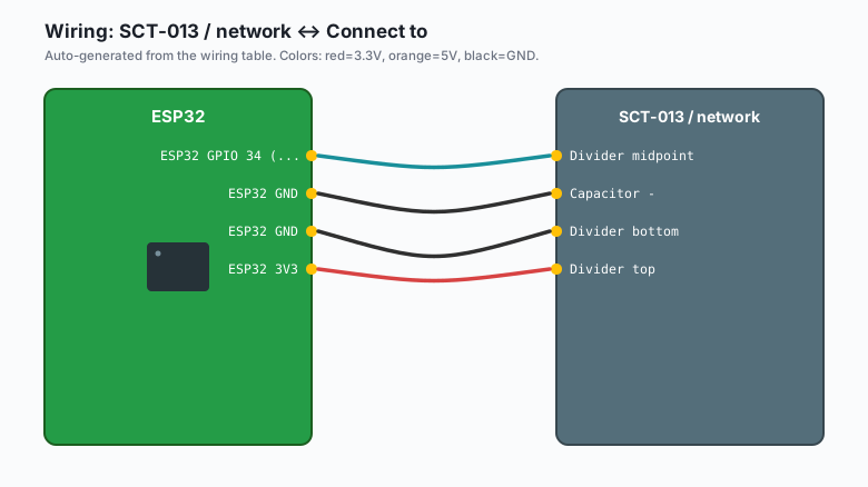
The bias network lifts the AC signal to mid-rail (1.65V on a 3.3V ESP32):
| SCT-013 / network | Connect to |
|---|---|
| SCT-013 tip (red) | Burden resistor top (SCT-013-000 only) AND 10K divider top AND ADC input |
| SCT-013 sleeve (black) | Burden resistor bottom (SCT-013-000 only) AND 10K divider bottom AND capacitor negative |
| Divider midpoint | ESP32 GPIO 34 (ADC1) |
| Capacitor + | Divider midpoint (same node as GPIO 34) |
| Capacitor - | ESP32 GND |
| Divider bottom | ESP32 GND |
| Divider top | ESP32 3V3 |
Concretely: the two 10K resistors in series sit between 3V3 and GND, and their midpoint is your new “zero current” reference at 1.65V. The SCT-013 output rides on top of that reference. The 10 uF cap stabilizes the midpoint against ADC sampling noise.
3V3 ----[10K]----+----[10K]---- GND
                 |
                 +---- GPIO 34 (with 10uF to GND)
                 |
              SCT-013 output (one lead)
                 |
        (other lead to GND for -030 variant)
With the SCT-013-030 (built-in burden), the secondary is just a signal source: connect one lead to the bias node and the other to GND. With the SCT-013-000, the burden resistor IS the load across the two secondary leads, and the same two leads also connect to the bias network. Do not double-burden the -030; adding a 33R across a sensor that already has one inside will halve your output.
The clamp goes around ONE conductor (hot or neutral, not both). Around both, the magnetic fields cancel and you read zero forever. This is the single most common “my CT reads nothing” cause, and no amount of code fixes it.
Install
Arduino IDE >> Sketch >> Include Library >> Manage Libraries >> search “EmonLib” >> install (OpenEnergyMonitor). EmonLib does the RMS math and the power factor calculation properly, so you do not have to hand-roll sampling. The raw version below is included anyway because understanding the math is half the point.
The code
ESP32 (Arduino) with EmonLib
#include "EmonLib.h"   // OpenEnergyMonitor EmonLib

EnergyMonitor emon1;

// SCT-013-030: 1V RMS at 30A. With the built-in burden treated as the
// load and the ADC reference at 3.3V, the classic OpenEnergyMonitor
// calibration constant for this combination is 30.
// For the SCT-013-000, compute it: CT ratio / burden ohms, then
// verify against a known load (section below). Empirical beats theory.
const float CALIBRATION = 30.0;   // for SCT-013-030
const float MAINS_VOLTS = 120.0;  // US; use 230.0 for EU/UK

void setup() {
  Serial.begin(115200);
  delay(1000);
  emon1.current(34, CALIBRATION);   // ADC pin, calibration constant
}

void loop() {
  // calcVI(samples, timeout_ms): sample for a fixed window
  emon1.calcVI(20, 2000);
  float realPower  = emon1.realPower;
  float appPower   = emon1.apparentPower;
  float powerF     = emon1.powerFactor;
  float rmsCurrent = emon1.Irms;

  Serial.print("Irms: ");
  Serial.print(rmsCurrent, 2);
  Serial.print(" A  real: ");
  Serial.print(realPower, 0);
  Serial.print(" W  PF: ");
  Serial.println(powerF, 2);
  delay(2000);
}
Raw ESP32 (Arduino) without EmonLib, so you can see the math
const int CT_PIN = 34;
const float ADC_REF = 3.3;
const float ADC_MAX = 4095.0;
const float CALIBRATION = 30.0;  // SCT-013-030: 30A per 1V RMS
const float MAINS_VOLTS = 120.0;

// Sample a window and compute RMS of (v - midpoint), then scale
float readIrmsAmps() {
  const int N = 200;
  double sumSq = 0;
  double sum = 0;
  for (int i = 0; i < N; i++) {
    int raw = analogRead(CT_PIN);
    double v = raw * ADC_REF / ADC_MAX;
    sum += v;
    sumSq += v * v;
    delayMicroseconds(500);   // ~1 kHz effective, fine for 60 Hz RMS
  }
  double mean = sum / N;
  double meanSq = sumSq / N;
  double variance = meanSq - mean * mean;
  double rmsVoltage = sqrt(variance);
  return rmsVoltage * CALIBRATION;
}

void setup() {
  Serial.begin(115200);
  analogReadResolution(12);
  delay(1000);
}

void loop() {
  float amps = readIrmsAmps();
  float watts = amps * MAINS_VOLTS;   // apparent power; PF ignored
  Serial.print("Irms: ");
  Serial.print(amps, 2);
  Serial.print(" A  ~");
  Serial.print(watts, 0);
  Serial.println(" W");
  delay(2000);
}
MicroPython
from machine import ADC, Pin
import time
import math

ct = ADC(Pin(34))
ct.atten(ADC.ATTN_11DB)   # full 0-3.3V range

CALIBRATION = 30.0   # SCT-013-030: 30A per 1V RMS
MAINS_VOLTS = 120.0

def read_irms_amps(n=200):
    readings = [ct.read_u16() for _ in range(n)]
    volts = [r / 65535 * 3.3 for r in readings]
    mean = sum(volts) / n
    rms = math.sqrt(sum((v - mean) ** 2 for v in volts) / n)
    return rms * CALIBRATION

while True:
    amps = read_irms_amps()
    watts = amps * MAINS_VOLTS
    print(f"Irms: {amps:.2f} A  ~{watts:.0f} W")
    time.sleep(2)
Calibrating against a known load
Constants get you close. A known load gets you right. Plug in a heater or a kettle with a printed wattage (e.g. a 1500W space heater), turn off everything else you can, and compare:
// If a 1500W heater reads 1290W, scale:
// newCalibration = CALIBRATION * (1500.0 / 1290.0);
Run that once, hardcode the corrected constant, and you are done. My unit came out at 27.8 instead of 30 after this step, which is a 7% error you would have lived with forever without checking.
What you learned
- A current transformer clamps around one conductor and never touches mains metal. The output is an AC voltage proportional to current.
- The -000 variant needs an external burden resistor; the -030 has one built in. Adding a burden to the -030 halves your output.
- The bias divider (2x 10K) lifts the AC signal to 1.65V so the whole AC waveform fits inside the ESP32’s 0 to 3.3V ADC window.
- RMS math turns the sampled AC waveform into amps; amps times your mains voltage (120 in the US, 230 in EU) turns amps into watts.
- Calibrate once against a known load and the reading becomes trustworthy within about 5%.
When something breaks
- Reading is flat zero. The clamp is around both conductors, or the clamp is not fully closed. The magnetic fields cancel around a pair. Move the clamp around a single hot wire (or use a plug-in splitter cord so you can clamp the individual conductors).
- Readings are negative or wildly noisy. The bias network is missing or wrong. Measure the divider midpoint with a multimeter: it must read about 1.65V. If it reads 3.3V or 0V, a divider resistor is in the wrong hole.
- Sensible numbers, wrong by a constant factor. Calibration. Run the known-load test above. Do not just scale to match your utility bill over a day (e.g. the meter includes the oven spike your bench test never sees); use a single known load.
- Values jump around between reads. You are sampling fewer than 2 full AC cycles, or other loads switch on mid-sample. Increase N to 500 in the raw version, or use EmonLib’s calcVI which samples for a fixed 250 ms window.
- Works on the bench, garbage in the panel. The clamp is picking up adjacent conductor fields, or your jumper leads are a long antenna. Keep the sensor leads short, twist them, and keep the CT away from the ESP32’s switching supply.
What to build next
- The ADS1115 external ADC tutorial is the precision upgrade: the ADS1115 has a differential input and a real PGA, which is exactly what a CT signal wants (e.g. 16 bits instead of 12, and no 0-3.3V range squeeze).
- The MQTT publish-subscribe tutorial publishes watts to your dashboard every 10 seconds.
- The ntfy notifications tutorial alerts your phone when whole-house draw exceeds a threshold (e.g. 8000W is a good “did I leave the dryer running” line).
- The Raspberry Pi InfluxDB Grafana tutorial stores the watts history and draws the graph your utility company will not.