ESP32: measure DC current with the ACS712 current sensor
Wire an ACS712 current sensor module to an ESP32 and measure DC current in amps. The right way to monitor power consumption of battery devices.
The ACS712 is the chip I reach for when I need to measure the current draw of a battery-powered device. It uses a Hall-effect sensor to measure the magnetic field around a current-carrying wire, so it is fully isolated from the circuit being measured. The output is a voltage proportional to current, with versions available for 5A, 20A, and 30A ranges.
This tutorial covers wiring, the zero-current calibration, the conversion formula, and the patterns for monitoring battery devices over time.
What you need
- ESP32 dev board
- ACS712 module (the breakout board with screw terminals; about $3).
Pick the right version for your current range:
- ACS712-05B: ±5A, 185 mV/A sensitivity
- ACS712-20A: ±20A, 100 mV/A sensitivity
- ACS712-30A: ±30A, 66 mV/A sensitivity
- 3 jumper wires
- Multimeter (for zero-current calibration)
Wiring
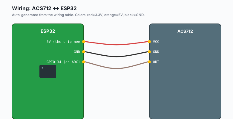
ACS712 VCC -- ESP32 5V (the chip needs 5V for full output range)
ACS712 GND -- ESP32 GND
ACS712 OUT -- ESP32 GPIO 34 (an ADC1 pin)
The ACS712’s output is centered at VCC/2 = 2.5V (when running on 5V). Current flowing one way pushes the voltage above 2.5V; current flowing the other way pushes it below 2.5V.
If you power the ACS712 from 5V and read it with an ESP32 running on 3.3V, the output range is 0-5V. The ESP32’s ADC can only read 0-3.3V. The ACS712 output can exceed 3.3V when current is high. Add a voltage divider on the output to keep it within range, or use the 3.3V variant of the module if available.
Some ACS712 modules have a 3.3V regulator on the output. Check yours. The Adafruit and SparkFun modules do.
The zero-current calibration
The ACS712’s output at zero current is not exactly VCC/2. It varies from sensor to sensor, typically 2.45-2.55V. You need to measure the actual zero-current output for your specific sensor:
const int ACS_PIN = 34;
float zeroCurrentVoltage;

void setup() {
  Serial.begin(115200);
  delay(1000);

  // Read the zero-current voltage 100 times and average
  long sum = 0;
  for (int i = 0; i < 100; i++) {
    sum += analogRead(ACS_PIN);
    delay(10);
  }
  float avgRaw = sum / 100.0;
  zeroCurrentVoltage = avgRaw * 3.3 / 4095.0;
  Serial.print("Zero current voltage: ");
  Serial.println(zeroCurrentVoltage, 4);
}

void loop() {
  // ...
}
Run this once with NO current flowing through the sensor’s input terminals (or with the input open). Write down the voltage. Hardcode it in the formula or save it to EEPROM.
The code
ESP32 (Arduino)
const int ACS_PIN = 34;
float zeroCurrentVoltage;

void setup() {
  Serial.begin(115200);
  delay(1000);

  long sum = 0;
  for (int i = 0; i < 100; i++) {
    sum += analogRead(ACS_PIN);
    delay(10);
  }
  float avgRaw = sum / 100.0;
  zeroCurrentVoltage = avgRaw * 3.3 / 4095.0;
  Serial.print("Zero current voltage: ");
  Serial.println(zeroCurrentVoltage, 4);
}

float readCurrentAmps() {
  int raw = analogRead(ACS_PIN);
  float voltage = raw * 3.3 / 4095.0;
  return (voltage - zeroCurrentVoltage) / 0.185;
}

void loop() {
  Serial.print("Current: ");
  Serial.print(readCurrentAmps());
  Serial.println(" A");
  delay(500);
}
Arduino (Uno, Nano, Mega)
const int ACS_PIN = A0;
float zeroCurrentVoltage;
const float VCC = 5.0;   // ACS712 powered from 5V; reference voltage is 5V
const float SENSITIVITY = 0.185;   // 5A version

void setup() {
  Serial.begin(9600);
  delay(1000);

  long sum = 0;
  for (int i = 0; i < 100; i++) {
    sum += analogRead(ACS_PIN);
    delay(10);
  }
  float avgRaw = sum / 100.0;
  zeroCurrentVoltage = (avgRaw / 1023.0) * VCC;
  Serial.print("Zero current voltage: ");
  Serial.println(zeroCurrentVoltage, 4);
}

float readCurrentAmps() {
  int raw = analogRead(ACS_PIN);
  float voltage = (raw / 1023.0) * VCC;
  return (voltage - zeroCurrentVoltage) / SENSITIVITY;
}

void loop() {
  Serial.print("Current: ");
  Serial.print(readCurrentAmps());
  Serial.println(" A");
  delay(500);
}
The Uno’s ADC is 10-bit (0-1023) and uses the 5V supply as reference. The ESP32 example uses 3.3V reference; the formula adapts to whichever reference your board uses.
MicroPython (ESP32 or Pico)
from machine import ADC, Pin
import time

# ESP32 ADC1: GPIO 34-39
# Pico ADC: GPIO 26-29
acs = ADC(Pin(34))
acs.atten(ADC.ATTN_11DB)

def calibrate():
    total = 0
    for _ in range(100):
        total += acs.read_u16()
        time.sleep_ms(10)
    avg = total / 100
    return (avg / 65535) * 3.3   # ESP32 3.3V reference

def read_current_amps(zero_v):
    raw = acs.read_u16()
    voltage = (raw / 65535) * 3.3
    return (voltage - zero_v) / 0.185

print('Calibrating, do not connect any load...')
zero = calibrate()
print(f'Zero voltage: {zero:.4f}')

while True:
    amps = read_current_amps(zero)
    print(f'Current: {amps:.3f} A')
    time.sleep_ms(500)
Raspberry Pi Python (with MCP3008 over SPI)
The ACS712 is ratiometric: its output is VCC/2 + sensitivity * current.
The MCP3008 reads voltages up to its Vref, so power the ACS712 from 3.3V
and use the Pi’s 3.3V reference. The ACS712-5A output range is then
1.65V (zero) ± 0.925V (±5A), well within the 0-3.3V input range.
from gpiozero import MCP3008
import time

acs = MCP3008(channel=0)
SENSITIVITY = 0.185   # ACS712-5A, in V/A; output is 1.65V + sensitivity * current

def calibrate():
    total = 0
    for _ in range(100):
        total += acs.value
        time.sleep(0.01)
    return (total / 100) * 3.3

def read_current_amps(zero_v):
    voltage = acs.value * 3.3
    return (voltage - zero_v) / SENSITIVITY

print('Calibrating, do not connect any load...')
zero = calibrate()
print(f'Zero voltage: {zero:.4f}')

while True:
    amps = read_current_amps(zero)
    print(f'Current: {amps:.3f} A')
    time.sleep(0.5)
What you should see
The reading is positive when current flows one way, negative when it flows the other way. The direction depends on how you connect the input terminals. If your readings come out negative when they should be positive, swap the input wires.
Calculating power and battery life
Current times voltage gives power. For a 12V battery powering a device drawing 0.5A:
power = 12V * 0.5A = 6 wattsFor battery life, multiply current by time:
void loop() {
  float amps = readCurrentAmps();
  float volts = readBatteryVoltage();   // from the 18650 tutorial
  float watts = amps * volts;
  Serial.print("Power: ");
  Serial.print(watts);
  Serial.println(" W");
  delay(1000);
}
For a battery capacity in watt-hours, divide by the average power to get runtime.
The noise problem
The ACS712’s output has some noise on it (a few mV peak-to-peak). For accurate readings, average:
float readCurrentAmpsSmoothed(int samples = 32) {
  long sum = 0;
  for (int i = 0; i < samples; i++) {
    sum += analogRead(ACS_PIN);
    delay(1);
  }
  float avgRaw = (float)sum / samples;
  float voltage = avgRaw * 3.3 / 4095.0;
  return (voltage - zeroCurrentVoltage) / SENSITIVITY;
}
32 samples at 1 ms each is 32 ms total. Fine for most projects.
For really clean readings, use an external ADC like the ADS1115 (16-bit I2C). The ACS712 + ADS1115 combination is the right way to do precision current measurement on the ESP32.
The “what is the device doing right now” project
A common use case is monitoring a device’s power state over time:
const float IDLE_THRESHOLD = 0.05;   // amps; below this = idle

void loop() {
  float amps = readCurrentAmpsSmoothed();
  if (amps > 1.0) {
    Serial.println("Device is ACTIVE");
  } else if (amps > IDLE_THRESHOLD) {
    Serial.println("Device is IDLE (low power mode)");
  } else {
    Serial.println("Device is SLEEPING (off)");
  }
  delay(500);
}
This pattern works for monitoring IoT devices, appliances, and any device where you want to know its operational state without modifying the device itself.
What you learned
- The ACS712 measures current using a Hall-effect sensor. Fully isolated from the measured circuit.
- Choose the right sensitivity (5A, 20A, or 30A) for your current range.
- Zero-current calibration is required. Measure with no current flowing.
- Average multiple readings to reduce noise.
When something breaks
- Readings are wildly wrong. Zero-current calibration is bad. Run the calibration again with the input wires disconnected.
- Reading is always 0. Sensor is not powered (5V required), or the input wires are not passing any current.
- Reading maxes out at the range. You picked the wrong sensitivity (e.g. 5A version measuring a 10A load).
- Reading is noisy even after averaging. Add a 100nF capacitor across the OUT pin and GND at the sensor.
What to build next
- The BME280 tutorial combines with this for a complete energy monitor: voltage, current, power, environment.
- The MQTT tutorial publishes current readings to a dashboard.
- The book ESP32 Energy Monitor covers building a whole-home electricity monitor with multiple ACS712 channels.