ESP32: drive a TLC5940 16-channel PWM LED driver
When the ESP32's LEDC peripheral is not enough, the TLC5940 adds 16 channels of 12-bit PWM over SPI. The right pick for big LED projects.
The ESP32’s LEDC peripheral gives you 16 PWM channels, which sounds like a lot until you try to drive 16 RGB LEDs (48 channels) or a 16-pixel WS2812-style array plus a few servos. The TLC5940 is the chip that fills the gap. It is a 16-channel, 12-bit PWM LED driver that takes grayscale data over SPI and drives constant-current outputs.
The trade: 12-bit per channel, 4096 steps instead of the LEDC’s 8-bit 256. Constant current means the chip itself limits the current through each LED; you do not need per-LED resistors. Daisy-chainable for 32, 48, 64+ channels.
I use TLC5940s when I have a project that needs more than 8 channels of smooth PWM. The LEDC is fine for motor speed control or a single RGB strip. The TLC5940 is for “I want every LED on this 16x16 matrix to fade smoothly.”
What you need
- ESP32 dev board (or Arduino Uno/Mega; the Mega is recommended because the Uno does not have enough RAM for large chains)
- TLC5940 chip (DIP-28, about $3)
- 16 LEDs + 2 kohm resistor for the IREF pin (sets the current)
- 0.1uF decoupling capacitor on each TLC5940’s VCC
- Breadboard, jumper wires
The TLC5940 is a 5V chip. The ESP32’s 3.3V logic works for the signal inputs; the LEDs need a separate 5V (or higher) supply. The outputs can switch up to 17V at 120 mA per channel.
Wiring
TLC5940 VCC  (pin 28) -- ESP32 5V
TLC5940 GND  (pin 1)  -- ESP32 GND
TLC5940 SIN  (pin 26) -- ESP32 GPIO 23  (serial data in, MOSI)
TLC5940 SCLK (pin 25) -- ESP32 GPIO 18  (shift clock, SCK)
TLC5940 BLANK(pin 23) -- ESP32 GPIO 5   (output blank, active HIGH)
TLC5940 XLAT (pin 24) -- ESP32 GPIO 17  (data latch)
TLC5940 GSCLK(pin 18) -- ESP32 GPIO 16  (PWM clock source, ~1 MHz)
TLC5940 DCPRG(pin 19) -- ESP32 GND     (use EEPROM dot correction, or VCC for default)
TLC5940 IREF (pin 20) -- 2 kohm resistor to GND  (sets LED current to ~20 mA)
TLC5940 VPRG (pin 27) -- ESP32 GND    (use grayscale data, not dot correction)

TLC5940 OUT0-OUT15     -- your 16 LEDs (cathode to OUT, anode to VLED)
VLED                   -- separate 5V supply (can share with ESP32 5V)
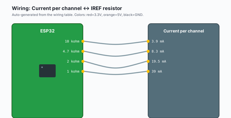
The IREF resistor is the key component. It sets the maximum current per channel:
| IREF resistor | Current per channel |
|---|---|
| 10 kohm | 3.9 mA |
| 4.7 kohm | 8.3 mA |
| 2 kohm | 19.5 mA |
| 1 kohm | 39 mA |
For standard 5mm LEDs at 20 mA, use 2 kohm. For high-brightness LEDs at 50 mA, use 820 ohm (but check the TLC5940’s 120 mA max per channel and 500 mA max per GND pin).
The ESP32 can supply 5V from the USB rail, but at 16 LEDs x 20 mA = 320 mA, that is too much for the USB-serial chip. Use an external 5V supply rated for at least 1A per TLC5940.
Install libraries
Sketch >> Include Library >> Manage Libraries >> search
Tlc5940 (by Alex Leone, the canonical Arduino library). Install
it.
The library works for both ESP32 and Arduino, but it requires you to define which pins are used. The defaults are for an Arduino Mega; for the ESP32, override the pin definitions:
#define TLC_SIN   23
#define TLC_SCLK  18
#define TLC_BLANK 5
#define TLC_XLAT  17
#define TLC_GSCLK 16
The code
ESP32 (Arduino)
#include <Tlc5940.h>

void setup() {
  Tlc.init();
  Tlc.clear();
}

void loop() {
  static uint16_t phase = 0;
  phase += 64;   // 0-4095

  for (int i = 0; i < NUM_TLCS * 16; i++) {
    // Sine wave per channel, offset so each channel is at a different phase
    float angle = (phase + i * 256) * 0.00076699;  // 2*pi/4096/2
    uint16_t brightness = 2047 + (uint16_t)(2047.0 * sin(angle));
    Tlc.set(i, brightness);
  }

  Tlc.update();
  delay(20);
}
The Tlc.set(channel, value) takes a channel index and a 12-bit
value (0-4095). Tlc.update() shifts the data to all the TLC5940
chips. The library handles all the SPI and PWM clock work.
Arduino (Uno, Nano, Mega)
Same code; the library auto-detects the board and uses the right default pins. The Mega can drive 5+ TLC5940s (80 channels); the Uno runs out of RAM around 3 chips.
#include <Tlc5940.h>

void setup() {
  Tlc.init(4095);   // max PWM value (default)
  Tlc.clear();
}

void loop() {
  for (int ch = 0; ch < NUM_TLCS * 16; ch++) {
    uint16_t value = (ch * 256 + millis()) & 0x0FFF;
    Tlc.set(ch, value);
  }
  Tlc.update();
  delay(20);
}
The TLC5940 needs a continuous PWM clock on GSCLK. The library uses a hardware timer to generate it; on the Uno, that means Timer1 is taken over. You cannot use the Servo library alongside the TLC5940 on the Uno.
Daisy-chaining
Wire SOUT (pin 17) of the first TLC5940 to SIN (pin 26) of the next.
Share SCLK, BLANK, XLAT, GSCLK. Now each Tlc.set() call writes
to all chips.
For N TLC5940s in a chain, the library expects you to set
NUM_TLCS:
#define NUM_TLCS 2 // 2 chips = 32 channelsChannel numbering: 0-15 are the first chip, 16-31 are the second, and so on. The library handles the byte order automatically.
Why 12-bit, not 8-bit
The LEDC peripheral gives you 8-bit PWM (256 steps). At 256 steps, the lowest non-zero value is 1/256 = 0.4% of full brightness. At 12 bits, the lowest value is 1/4096 = 0.024%. That is a 16x improvement in low-end smoothness, which matters for:
- Sunset/sunrise fades (the bottom 5% of brightness is the most visible)
- Color mixing at low brightness
- Dim indicator LEDs that need to fade in slowly
For a 16-bit TLC59401 variant, 65,536 steps. The improvement over 12-bit is not visually noticeable in 99% of projects.
When the LEDC is enough vs. when you need a TLC5940
The LEDC is enough when:
- 8 or fewer channels
- 8-bit resolution is fine (indicator LEDs, motor speed)
- 5 kHz+ PWM frequency is OK
- The project is one chip, no daisy chain
You need a TLC5940 (or similar) when:
- 16+ channels of PWM
- 12-bit resolution matters (color mixing, smooth fades)
- The LEDs need constant-current drive (e.g. you do not want to hand-match 16 resistors)
- Daisy-chaining is useful (the next LED project is always bigger than the current one)
What you learned
- The TLC5940 is 16 channels of 12-bit PWM over SPI.
- IREF resistor sets the per-channel current.
- Daisy-chainable; the library handles the byte ordering.
- Constant current means no per-LED resistors.
When something breaks
- LEDs are very dim or off. IREF resistor value is wrong. For 20 mA per channel, use 2 kohm.
- All LEDs flicker at the same rate. GSCLK pin not generating the PWM clock. Check the wiring; the library assumes ESP32 GPIO 16 can output a high-frequency clock.
- Library fails to compile on ESP32. The default pin definitions are for the Mega. Override them in your sketch (see “Install libraries” above).
- The first chip works, the rest are garbled. Daisy chain wiring issue. SOUT (pin 17) to SIN (pin 26). XLAT and SCLK must be shared.
- LEDs are red when they should be off. OUT pins are not truly off. The TLC5940 has a minimum off-state current of about 1 uA. For zero light, use BLANK to disable all outputs.
What to build next
- The PWM with LEDC tutorial covers the in-chip peripheral (cheaper, but limited to 16 channels).
- The WS2812B tutorial is the right pick for individually- addressable RGB strips. No PWM chip needed; the data encoding is in the LED.
- The book ESP32 in Production has a 96-channel LED art project built from 6 TLC5940s.