Arduino: a full traffic light with pedestrian button
Build a traffic light with a pedestrian crossing button using a proper state machine. The project that teaches event timing without delay().
A traffic light looks like the simplest project on earth (three LEDs,
blink them in order) and turns out to be the best introduction to the
single most useful idea in embedded programming: the state machine
with a timer. Real traffic lights are event-driven, not delay-driven.
Pedestrians press buttons. Lights must not skip states when you press
twice. The delay()-based version everyone writes first cannot do any
of that.
This version handles a pedestrian button, all-green-safety timing, and
a walk phase with a countdown, without a single delay() in the loop.
What you need
- Arduino Uno
- 5x LEDs: red, yellow, green (car), plus red and green (pedestrian), or two 3-LED traffic-light modules (about $3)
- 5x 220 ohm resistors
- A momentary pushbutton
- Breadboard and wires
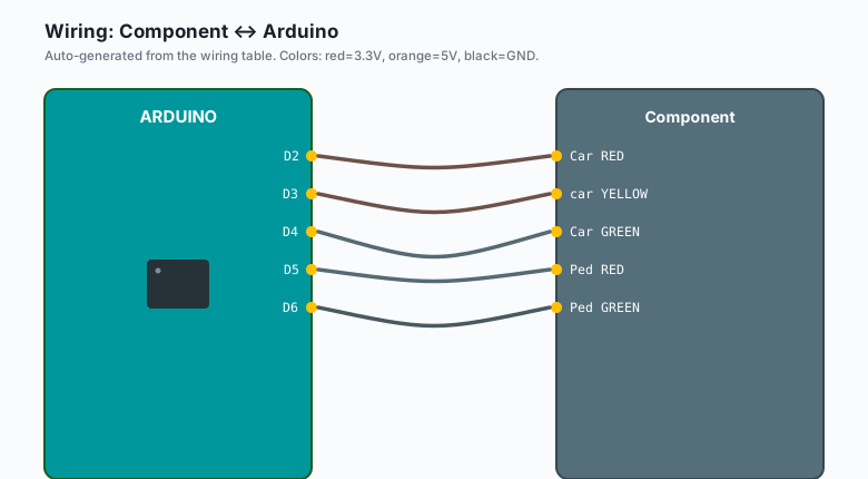
Wiring
| Component | Arduino |
|---|---|
| Car RED | D2 |
| car YELLOW | D3 |
| Car GREEN | D4 |
| Ped RED | D5 |
| Ped GREEN | D6 |
| Button | D7 to GND (INPUT_PULLUP, no resistor) |
LEDs get their 220-ohm resistor in series, cathode to GND. The button uses the pin’s internal pull-up (pressed = LOW), which is why no external resistor is needed.
The state machine
| State | Car | Ped | Duration | Next |
|---|---|---|---|---|
| CARS_GREEN | green | red | 10 s (or 20 s min) | CARS_YELLOW |
| CARS_YELLOW | yellow | red | 2 s | ALL_RED_1 |
| ALL_RED_1 | red | red | 1 s | PED_WALK |
| PED_WALK | red | green | 8 s | PED_FLASH |
| PED_FLASH | red | red blink | 3 s | ALL_RED_2 |
| ALL_RED_2 | red | red | 1 s | CARS_GREEN |
The two all-red phases are not decoration: they are the safety gap. Traffic engineers give pedestrians a head start and cars a clearance window (e.g. skip them and you have built a toy that teaches bad habits).
The code
// Millis-based state machine. No delay() anywhere.
enum State { CARS_GREEN, CARS_YELLOW, ALL_RED_1, PED_WALK, PED_FLASH, ALL_RED_2 };

const unsigned long STATE_TIME[] = {20000, 2000, 1000, 8000, 3000, 1000};
const int PED_WALK_END = 8000;   // ms into PED_FLASH that counts down

State state = CARS_GREEN;
unsigned long stateStart = 0;
bool walkRequested = false;

const int L = {2, 3, 4, 5, 6}[0];  // see pin table: 2=car R,3=Y,4=G,5=ped R,6=ped G
const int BTN = 7;

void setLights(bool cr, bool cy, bool cg, bool pr, bool pg) {
  digitalWrite(2, cr); digitalWrite(3, cy); digitalWrite(4, cg);
  digitalWrite(5, pr); digitalWrite(6, pg);
}

void setup() {
  for (int p = 2; p <= 6; p++) pinMode(p, OUTPUT);
  pinMode(BTN, INPUT_PULLUP);
  enter(CARS_GREEN);
}

void enter(State s) {
  state = s;
  stateStart = millis();
  switch (s) {
    case CARS_GREEN:  setLights(0,0,1, 1,0); break;
    case CARS_YELLOW: setLights(0,1,0, 1,0); break;
    case ALL_RED_1:
    case ALL_RED_2:   setLights(1,0,0, 1,0); break;
    case PED_WALK:    setLights(1,0,0, 0,1); break;
    case PED_FLASH:   setLights(1,0,0, 1,0); break;   // blink handled in loop
  }
}

void loop() {
  unsigned long t = millis() - stateStart;

  // Button: only meaningful during CARS_GREEN, and only shortens.
  if (state == CARS_GREEN && digitalRead(BTN) == LOW) {
    if (t > 8000) stateStart -= (20000 - 8000);   // cut green to 8 s more
  }

  // Pedestrian blinking during PED_FLASH
  if (state == PED_FLASH) {
    digitalWrite(6, (t / 300) % 2);   // blink ped green at ~3 Hz
  }

  if (t >= STATE_TIME[state]) {
    switch (state) {
      case CARS_GREEN:  enter(CARS_YELLOW); break;
      case CARS_YELLOW: enter(ALL_RED_1);   break;
      case ALL_RED_1:   enter(PED_WALK);    break;
      case PED_WALK:    enter(PED_FLASH);   break;
      case PED_FLASH:   enter(ALL_RED_2);   break;
      case ALL_RED_2:   enter(CARS_GREEN);  break;
    }
  }
}
The two ideas that generalize
Millis over delay. delay(20000) would freeze the whole program:
the button would need to be held at the exact right instant to ever
register. The millis-diff pattern keeps loop() spinning thousands of
times per second, so the button check always works (e.g. this exact
pattern runs sprinkler controllers, greenhouse vents, and every
multi-actuator project worth building).
States as a table, not as logic. The timing array and the transition switch ARE the whole program. Adding a “flashing yellow at night” mode is adding a state, not re-threading more flags through if-statements. When a project’s behavior is described in a table, write the table in code.
What you learned
- Event timing with millis() instead of delay().
- The state machine table: states, durations, transitions.
- INPUT_PULLUP for buttons (pressed = LOW) with zero extra parts.
When something breaks
- Button acts pressed at random: you wired the button without pull-up and the pin floats. INPUT_PULLUP is the fix.
- Lights stuck on one state: the STATE_TIME array is out of order relative to the enum. Keep them side by side in the code and edit them together.
- Ped green never comes: the all-red phases look like “nothing is happening” and get “optimized” away. They are load-bearing.
- Blink phase runs forever: the blink code and the state-exit check both live in loop(); if you put the blink inside a for-loop with delays, the exit check never runs. Keep blink as a millisecond-parity trick, not a loop.
What to build next
- The line-follower robot uses the same decision-table thinking with sensors instead of a schedule.
- Add a second button + buzzer for a “walk request confirmed” beep.
- Wire the car light through a relay module and you control a real 12V lamp, same code.