ESP32: record audio with an INMP441 I2S microphone
Wire a $3 INMP441 MEMS mic to the ESP32 and capture real audio over I2S. The hardware path to sound detection, voice notes, and wake words.
The ESP32 has an I2S peripheral built in, and the INMP441 is the microphone that takes advantage of it: a MEMS mic that outputs digital audio directly, no amplifier stage, no noise floor from a long analog wire. Together they record real 16-bit audio for about $4 in parts.
This is the hardware half of every “ESP32 hears something” project: sound detection, clap triggers, voice notes to a server, wake words.
What you need
- ESP32 dev board
- INMP441 MEMS microphone module (the little purple board, about $3)
- 6 jumper wires
Why the INMP441 over an analog mic module (e.g. the MAX9814 boards): the analog route is simpler to wire but every centimeter of wire picks up noise, and the ESP32’s ADC is the weak part of the chip. I2S is digital end to end: the mic does the analog work centimeters from the capsule and ships clean bits.
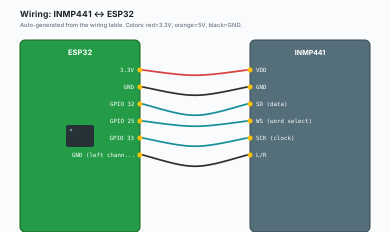
Wiring (I2S)
| INMP441 | ESP32 |
|---|---|
| VDD | 3.3V |
GND | GND |
SD (data) | GPIO 32 |
| WS (word select) | GPIO 25 |
SCK (clock) | GPIO 33 |
| L/R | GND (left channel) |
The L/R pin selects which stereo half the mic answers on. Ground it for left. (Two mics on one bus is how stereo recording works: one with L/R grounded, one to VDD.)
The code
#include <driver/i2s.h>

#define I2S_WS   25
#define I2S_SD   32
#define I2S_SCK  33
#define SAMPLE_RATE 16000
#define SAMPLE_BUF 256

void setup() {
  Serial.begin(115200);

  i2s_config_t i2s_config = {
    .mode = (i2s_mode_t)(I2S_MODE_MASTER | I2S_MODE_RX),
    .sample_rate = SAMPLE_RATE,
    .bits_per_sample = I2S_BITS_PER_SAMPLE_32BIT,
    .channel_format = I2S_CHANNEL_FMT_ONLY_LEFT,
    .communication_format = I2S_COMM_FORMAT_STAND_I2S,
    .intr_alloc_flags = ESP_INTR_FLAG_LEVEL1,
    .dma_buf_count = 8,
    .dma_buf_len = 64,
    .use_apll = false
  };

  i2s_pin_config_t pins = {
    .bck_io_num = I2S_SCK,
    .ws_io_num = I2S_WS,
    .data_out_num = I2S_PIN_NO_CHANGE,
    .data_in_num = I2S_SD
  };

  i2s_driver_install(I2S_NUM_0, &i2s_config, 0, NULL);
  i2s_set_pin(I2S_NUM_0, &pins);
  Serial.println("I2S mic ready");
}

void loop() {
  int32_t raw[SAMPLE_BUF];
  size_t bytesRead;

  i2s_read(I2S_NUM_0, raw, sizeof(raw), &bytesRead, portMAX_DELAY);
  int samples = bytesRead / sizeof(int32_t);

  // Simple loudness: peak absolute sample this buffer
  int32_t peak = 0;
  for (int i = 0; i < samples; i++) {
    int32_t v = raw[i] >> 14;   // INMP441 is 24-bit in a 32-bit frame; shift to sane range
    if (v < 0) v = -v;
    if (v > peak) peak = v;
  }

  Serial.println(peak);
}
Upload, open Serial Monitor. Quiet room prints low hundreds; clap next to the mic and the peak jumps into the tens of thousands. You have working audio.
Getting real audio out (WAV)
The peak meter proves capture works. For actual recording, buffer to PSRAM and write a WAV (e.g. header plus the raw PCM):
// WAV header = 44 bytes of structure + your samples
// Sample rate 16000, 16-bit mono, then write the int32 buffer
// (converted down: sample >> 11 gives 16-bit range)
The full pattern: capture N seconds into PSRAM, sample >> 11 each
into a 16-bit array, write a 44-byte WAV header with your rate and
length, then ship it over HTTP POST to any server (e.g. upload to the
Pi on your LAN, or push the file with the ntfy attachment pattern).
The loudness meter, done right
Peak is a crude meter (a single click spikes it). For “is someone talking in this room” you want RMS (square, average, square-root), which ignores single-sample spikes and tracks actual energy:
uint64_t sum = 0;
for (int i = 0; i < samples; i++) {
  int32_t v = raw[i] >> 14;
  sum += (int64_t)v * v;
}
float rms = sqrt((float)(sum / samples));
Threshold a smoothed RMS (e.g. moving average of 10 buffers) and you have a sound-activated anything, with about one false trigger a day instead of ten.
What you learned
- I2S is the digital audio bus; the INMP441 is the cheap clean mic for it.
- The driver install + set_pin pattern is the whole setup.
- Peak vs RMS: peak for clicks, RMS for “is there sound”.
When something breaks
- All zeros forever: L/R pin floating (tie it), or SD/WS swapped. The I2S RX will happily read silence forever with wrong wiring.
- Noise floor huge and constant: the mic is picking up the power rail. Use a short 3.3V supply straight from the dev board, not a breadboard rail shared with LEDs.
- Reading half what you expect: the 32-bit samples are 24-bit values left-aligned; the shift constant controls your range. There is no “wrong” here, just be consistent across captures.
- Works, then stops after minutes: you are not calling i2s_read() fast enough and the DMA buffers are full. Read in a tight loop or use a FreeRTOS task for audio.
What to build next
- The wake word tutorial runs a keyword model on exactly this capture path.
- A clap-triggered light: RMS threshold + the relay tutorial.
- The book IoT with ESP32 bundles the sensor tutorials.