Arduino: drive a 4-digit display with the TM1637
Wire a TM1637 4-digit 7-segment display to an Arduino and print numbers, a clock, and a scrolling counter. Two pins, one library, no soldering.
The TM1637 4-digit display is the readout I reach for when a project needs to show a number without a laptop attached. Four digits, a colon in the middle, one chip on the back doing all the segment multiplexing, and a two-pin interface that leaves half the Arduino free (e.g. a temperature probe on one pin, a button on another, and the display on the last two). It costs about $2 and it is on every bench eventually.
The trap: the colon. On the popular red 0.56-inch modules the colon is not a segment you set like any other. It is bit 7 of the third byte you send, and some library versions toggle it with a separate method while others expect you to flip the bit yourself. My first clock showed “1234” or “12:34” depending on which example I had copied. The other trap is power: a module driven from 5V at full brightness pulls enough current that a weak USB port makes the display flicker or the Arduino brown out. Use a real supply if you push brightness up.
What you need
Needed
| Item | Qty | Purpose | Est. cost |
|---|---|---|---|
| Arduino Uno or Nano | 1 | the brain | $10-$25 |
| TM1637 4-digit display module (0.36 or 0.56 inch, red or blue) | 1 | the readout | $2 |
| Jumper wires (female-to-male if your module has a pin header) | 4 | connections | $1 |
The 0.56-inch module has the colon between digits 2 and 3 and is the one to buy for clock projects. The 0.36-inch version is what ships in most electronic kits. Six-digit modules labeled “TM1637” are usually a different driver (the TM1638, which speaks a different protocol), so match the chip to the library.
Nice to have
- Multimeter to verify 5V actually arrives at the module when it looks dim (the #1 “display acts haunted” cause)
- Soldering iron and solder only if your module came with an unsoldered header
- Helping hands to hold the header straight while it cools
- Wire stripper for custom-length jumpers
- Iron stand and soldering mat for a calm bench
Wiring
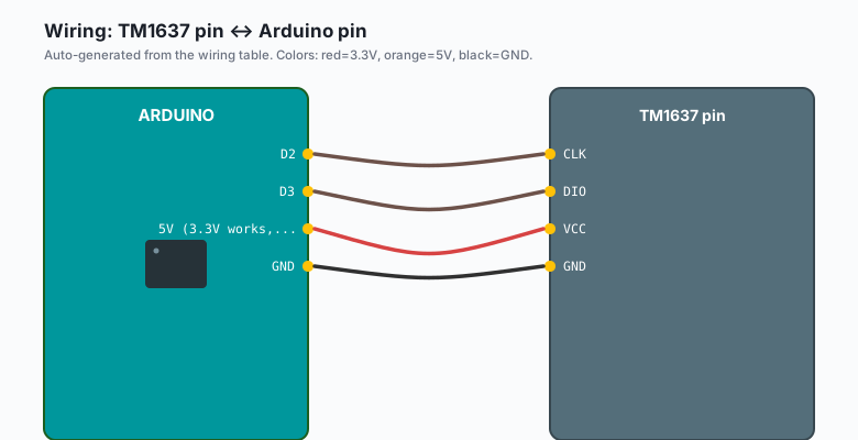
| TM1637 pin | Arduino pin |
|---|---|
CLK | D2 |
| DIO | D3 |
VCC | 5V (3.3V works, dimmer) |
GND | GND |
CLK and DIO are not I2C despite looking like it. The TM1637 speaks its own two-wire protocol, so the pins are arbitrary and the library bit-bangs them. Any two free digital pins will do (e.g. D2 and D3 here, D5 and D6 on a crowded board).
On an ESP32 the module runs from 3.3V and the logic levels match, so it is a drop-in swap: CLK and DIO to GPIO 26 and 27, VCC to 3V3. It will be visibly dimmer than the 5V Uno build, which is normal.
Install
Arduino IDE >> Sketch >> Include Library >> Manage Libraries >> search
“TM1637” >> install TM1637 by Avishay Orpaz. That is the library
with the TM1637Display class every example uses, and it drives both
the Seeed Grove module and the generic red boards. (Seeed’s own “Grove
4-Digit Display” library also exists in the list and has a different
class name; if TM1637Display does not compile, the wrong one is
installed.)
The code
The whole API is six calls. This sketch uses all of them:
#include <TM1637Display.h>

#define CLK 2
#define DIO 3

TM1637Display display(CLK, DIO);

void setup() {
  display.setBrightness(5);          // 0 (dim) to 7 (blinding)
  display.clear();
}

void loop() {
  // 1. Raw number, right-aligned
  display.showNumberDec(42);

  delay(1500);

  // 2. Fixed width with leading zeros (e.g. 0007 instead of a bare 7)
  display.showNumberDecEx(7, 0, true);

  delay(1500);

  // 3. Colon on, for clock displays: 12:34
  //    0b01000000 turns on the colon bit on 0.56" modules
  display.showNumberDecEx(1234, 0b01000000);

  delay(1500);

  // 4. Individual segments: draw "AbC-" as a demo
  uint8_t segments[] = {
    SEG_A | SEG_B | SEG_C | SEG_E | SEG_F | SEG_G,  // 'A'
    SEG_A | SEG_B | SEG_E | SEG_F | SEG_G,          // 'b'
    SEG_A | SEG_D | SEG_E | SEG_F,                  // 'C'
    SEG_G                                           // '-'
  };
  display.setSegments(segments);

  delay(1500);

  // 5. Set just one digit and keep the rest (e.g. a battery digit)
  display.showNumberDec(0, false, 1, 3);  // digit 3 = rightmost = 0

  delay(1500);
}
setBrightness() takes 0 to 7 and the difference between 1 and 7 is
night and day on current draw. Below about 3 the display is readable in
a dim room; 7 is for daylight.
A counter with debounce, the real pattern
Numbers that change are more interesting than numbers that sit. This is the counter pattern: one button adds a count, the display shows it, and a software debounce keeps one press equal to one increment.
#include <TM1637Display.h>
#include <ezButton.h>

#define CLK 2
#define DIO 3
#define BUTTON 4

TM1637Display display(CLK, DIO);
ezButton button(BUTTON);

int count = 0;

void setup() {
  display.setBrightness(5);
  display.showNumberDec(0);
}

void loop() {
  button.loop();

  if (button.isPressed()) {
    count++;
    if (count > 9999) count = 0;   // wrap: the display only has four digits
    display.showNumberDec(count);
  }
}
The ezButton library (install from Library Manager the same way) does the debouncing internally. Without it, one physical press registers three or four counts and the display jumps in threes.
Building a clock with it
For a clock you need the colon and a time source. The colon from the sketch above plus the DS3231 RTC (the tutorial on this site covers it) gives you a clock that keeps time through power loss:
// Inside loop(): read hours and minutes from a DS3231, then
display.showNumberDecEx(hours * 100 + minutes, 0b01000000);
The DS3231 tutorial’s code produces hours and minutes directly; the
display line is the only new part. That build (RTC + TM1637 + two
buttons for setting) is the classic first real project and the
DS3231 RTC OLED clock tutorial is the bigger sibling with a nicer
screen.
What you learned
- The TM1637 does the segment multiplexing on-module, so four digits cost two Arduino pins and almost no current per segment.
showNumberDecEx()with the colon mask is the clock call; plainshowNumberDec()covers everything else.- Multiplexed displays dim at high brightness because each digit is only actually lit a fraction of the time (the duty cycle, not the supply, is the limit).
When something breaks
- Display shows nothing: VCC and GND are swapped (the pin order on cheap modules varies), or brightness is 0. Set brightness first, then debug the wiring.
- Random segments light and the sketch still runs: CLK and DIO are swapped. Swap the two wires; nothing else needs to change.
- Dim at high brightness: the module is on 3.3V, or the USB port cannot supply the current. Move VCC to 5V or a powered hub.
- Counts jump by more than one per press: no debouncing. Use
ezButton as above, or add a
delay(50)after each press as the quick-and-dirty version. - Colon will not light: your module uses a different colon bit. Try
0b01000000first, then0b00100000. One of the two matches.
What to build next
- The DS3231 RTC plus this display is a mains-powered desk clock that survives outages; add the membrane keypad for setting it without a laptop.
- The traffic light tutorial with a TM1637 countdown as the pedestrian signal (3, 2, 1, walk) is a satisfying afternoon.
- The electronic dice tutorial rolls on the same 4-digit driver if you want a two-dice, one-button version.
- The MAX6675 thermocouple tutorial plus this display is a high-temp bench thermometer for about $12 total.
The book Arduino Robotics bundles the display and input tutorials including this one.