Arduino: receive 433 MHz RF remote signals and replay them
Sniff, decode, and replay 433 MHz RF remotes (wireless doorbells, plug sockets) with a superheterodyne receiver and RCSwitch. One Arduino, two boards.
Every 433 MHz wireless device in your house speaks the same language: on/off keying, a preamble, an address, a command. Wireless doorbells, mains plug sockets, that one car’s keyfob era before rolling codes. The parts are $3: one receiver to listen, one transmitter to talk. The project that pays for itself immediately is the replay build: an Arduino that records what your doorbell button sends, then sends it back so your automation can ring its own doorbell (or switch its own mains sockets, which is the use case with actual stakes).
The trap: the $1 green receiver module (the SYN470/XY-MK-5V square one) barely works, and it makes people conclude the whole project is flaky. It is not the project. The superheterodyne receiver (the RXB6, or the WL101-100-243 module shaped like a silver slab) costs one dollar more and has roughly 10x the usable range and none of the constant-noise behavior. Buy the superhet first. I own a drawer of the cheap ones so you do not have to.
What you need
Needed
| Item | Qty | Purpose | Est. cost |
|---|---|---|---|
| Arduino Uno or Nano | 1 | decodes and transmits | $10-$25 |
| RXB6 or WL101-100-243 superheterodyne 433 MHz receiver | 1 | listens; the good receiver, not the $1 green one | $3 |
| FS1000A 433 MHz transmitter module | 1 | replays the captured signal | $2 |
| 17.3 cm wire (single strand) | 2 | antennas, one per module; the length is not decorative | $0 |
| Any 433 MHz remote or wireless plug | 1 | the signal source you are capturing | $5-$10 |
| Jumper wires | 8 | connections | $1 |
Nice to have
- Breadboard: the receiver and transmitter sit on opposite ends, and breadboard real estate keeps them 10 cm apart (the transmitter swamps the receiver when both are active otherwise)
- Multimeter: confirms the modules’ 5V before you blame the library for dead air
- Wire stripper: cutting two exact 17.3 cm antennas beats guessing (a quarter wavelength at 433 MHz)
- Helping hands: holds the wire while you solder or twist the antenna onto the ANT pad
- Soldering iron + solder: the ANT pad takes a soldered antenna best; the through-hole is too big for most jumper pins
- Soldering mat and iron stand: the standard desk-protection pair
- Magnifying goggles: the module silkscreen pin labels are small and occasionally wrong, trust the datasheet pinout
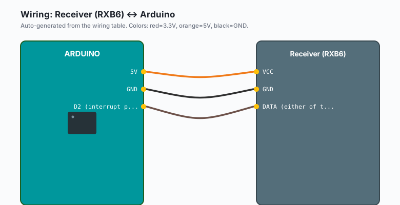
Wiring
| Receiver (RXB6) | Arduino |
|---|---|
VCC | 5V |
GND | GND |
DATA (either of the two) | D2 (interrupt pin) |
| ANT | 17.3 cm wire |
| Transmitter (FS1000A) | Arduino |
|---|---|
VCC | 5V |
GND | GND |
DATA | D12 |
| ANT | 17.3 cm wire |
Keep the transmitter’s antenna as far from the receiver as your desk allows during development. A transmitting antenna next to a receiving one saturates the receiver’s front end and you will read it as “library broke after I added transmit code”.
Install
Arduino IDE >> Sketch >> Include Library >> Manage Libraries >> search “RCSwitch” >> install the one by sui (Porsche-Inter-Aut- omotive maintains forks, but the original still works for both directions: receive and transmit).
One library does both halves of this project. That is the reason I pick RCSwitch over the ping-pong alternatives (rc-switch for receiving, RCSend for sending, and no shared vocabulary between them).
The code
Sketch 1: capture. Listens, prints every protocol, bit length, and binary payload it sees. Press your remote or doorbell button.
#include <RCSwitch.h>

RCSwitch mySwitch;

void setup() {
  Serial.begin(115200);
  mySwitch.enableReceive(0);   // interrupt 0 = pin D2 on Uno/Nano
  Serial.println("Listening on 433 MHz...");
}

void loop() {
  if (mySwitch.available()) {
    Serial.print("Protocol: ");
    Serial.print(mySwitch.getReceivedProtocol());
    Serial.print("  bits: ");
    Serial.print(mySwitch.getReceivedBitlength());
    Serial.print("  value: ");
    Serial.print(mySwitch.getReceivedValue(), BIN);
    Serial.print("  (decimal ");
    Serial.print(mySwitch.getReceivedValue());
    Serial.println(")");
    mySwitch.resetAvailable();
  }
}
Sketch 2: replay. Fill in the three numbers you captured.
#include <RCSwitch.h>

RCSwitch mySwitch;

const unsigned long VALUE   = 1234567;  // from the capture sketch
const unsigned int  BITLEN  = 24;       // from the capture sketch
const byte          PROTOCOL = 1;       // from the capture sketch

void setup() {
  Serial.begin(115200);
  mySwitch.enableTransmit(12);          // FS1000A DATA pin
  mySwitch.setProtocol(PROTOCOL);
  mySwitch.setRepeatTransmit(5);        // send it 5x; RF has no ACK
}

void loop() {
  mySwitch.send(VALUE, BITLEN);
  Serial.println("sent");
  delay(5000);
}
Open the Serial Monitor at 115200, press the remote, and write down the three numbers (protocol, bit length, value). Plug them into the replay sketch. Fire the replay at the wireless socket and watch it click. If nothing happens, re-run the capture and check whether the button sends two different values (some remotes alternate A/B payloads per press to defeat simple repeaters; replay whichever one your device accepts).
What the numbers mean
- Protocol: the timing template (pulse widths) for this device’s encoding. Protocol 1 covers the huge family of EV152K/PT2262-style chips in cheap remotes and sockets.
- Bit length: how long the payload is (24 bits is the common address+data layout for the socket remotes).
- Value: the actual bits, which include the fixed address of the device. Two buttons on the same remote share the address and differ in the low bits.
The security caveat is real and worth naming plainly: this protocol family has no encryption and no rolling code. You can replay your own doorbell and your own plugs; so can anyone with the same $3 of hardware. Do not use it to open anything you would not leave unlocked (e.g. a garage with rolling-code security is a different system entirely and this tutorial does not apply to it).
What you learned
- 433 MHz “remotes” are just OOK bit-bangs: once decoded, they are three numbers (protocol, length, value) and nothing more.
- The receiver module is the quality bottleneck: superheterodyne beats regenerative by an order of magnitude for one dollar.
- RF has no acknowledgment, so transmitters repeat; your replay
sketch needs
setRepeatTransmitfor the same reason.
When something breaks
- Capture sketch prints nothing: antenna missing (the onboard trace antenna on cheap receivers is nearly useless), wrong pin (must be interrupt 0 = D2 on an Uno), or the green regenerative receiver in play. Swap in the superhet first, it fixes 90% of “no data”.
- Captured values differ every press: the remote is using a rolling code (KeeLoq family, common on car fobs and decent garage openers). RCSwitch cannot replay those by design; this is a hardware limitation, not a bug.
- Replay sends but the socket ignores it: protocol or bit length mismatch. Re-run capture while pressing the exact button you want to clone, and use those exact three numbers.
- Works at 1 m, fails at 5 m: transmitter power and antenna. 12V on the FS1000A’s VCC is rated and allowed (DATA must then be level-shifted to 12V too, a transistor stage does it), and a proper 17.3 cm straight antenna is worth more than any code change.
- Receiver spams garbage with no remote nearby: noise. Keep the receiver’s antenna short and the module away from the USB port and switching supplies; a 100 nF cap across VCC/GND helps.
What to build next
- The relay control tutorial plus this one: the Arduino replays the socket remote’s address and then drives real loads directly, skipping the wireless middleman.
- The IR receiver tutorial is the infrared sibling: same capture-decode-replay arc, for remotes instead of sockets.
- The nRF24L01 tutorial is the upgrade when you want real two-way, addressed, acknowledged Arduino-to-Arduino links on hardware you control end to end.
- The 8x8 LED matrix makes a satisfying “signal received” indicator panel for the doorway where your doorbell lives.