Arduino: read high temperatures with a K-type thermocouple and MAX6675
Wire a K-type thermocouple and a MAX6675 to an Arduino and read oven, kiln, and solder-pot temperatures up to 1024 C. Includes the polarity trap.
Every Arduino temperature tutorial stops at 125 C because that is where the DS18B20 dies. The moment your project involves an oven, a kiln, a coffee roaster, or a solder pot (e.g. any of the 150-450 C jobs), you need a thermocouple. A K-type probe plus a MAX6675 converter chip reads up to 1024 C in 0.25 C steps, and the pair costs about $7 all in.
The trap: my first thermocouple read backwards. I wired the probe’s red wire to the terminal marked + because red is positive on every other sensor I own. On US color-coded K-type wire, red is the NEGATIVE leg and yellow is the positive one. With the legs swapped, heating the probe made the reading fall instead of climb. Two more traps wait behind it: the MAX6675 needs 220 ms per conversion, so a loop with no delay returns zeros and garbage, and the chip measures the temperature of its own board to do cold-junction compensation, so the module itself has to stay out of the heat.
What you need
Needed
| Item | Qty | Purpose | Est. cost |
|---|---|---|---|
| Arduino Uno or Nano | 1 | the brain | $10-$25 |
| MAX6675 module (purple board, two-position screw terminal) | 1 | thermocouple-to-digital converter | $3 |
| K-type thermocouple probe | 1 | the sensor (pick the range you need) | $4 |
| Jumper wires (female-to-male if your module has a header) | 5 | connections | $2 |
Probes come with different tips and temperature ratings. A glass-braid K-type probe is good to about +450 C and survives a toaster oven. For kiln work you want a ceramic-tipped probe rated past +1000 C. The MAX6675 caps everything at +1024 C either way; below 0 C it also reads nothing, so freezer logging needs the MAX31855K instead.
Nice to have
- Soldering iron and solder if your probe has bare leads you want solidly attached instead of trapped under the terminal screws
- Iron stand and helping hands: hold the probe while you work the terminals
- Wire stripper for making clean ends
- Multimeter to check probe continuity before blaming the chip
- Anti-static wristband and soldering mat for a calm bench
Wiring
| MAX6675 pin | Arduino pin |
|---|---|
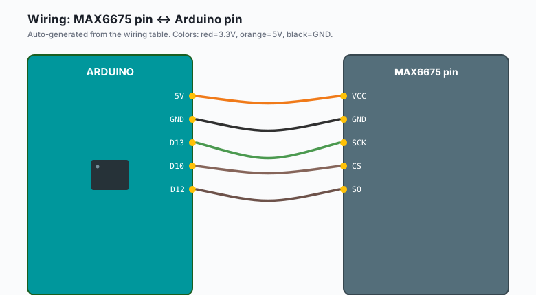
VCC | 5V |
GND | GND |
SCK | D13 |
CS | D10 |
| SO | D12 |
The thermocouple lands on the module’s screw terminal: yellow wire to the terminal marked + (or T+), red wire to - (T-). If your probe has no color coding, wire it one way, squeeze the tip between two fingers, and watch the reading. It should climb a degree or two. If it falls, swap the legs.
Keep the module itself at room temperature. The MAX6675 measures the temperature of its own terminals to subtract the cold-junction offset, so a module mounted inside the oven enclosure reads the oven, not the probe. Mount it outside and let the probe wire run in.
Install
Arduino IDE >> Sketch >> Include Library >> Manage Libraries >> search “MAX6675” >> install Adafruit MAX6675 Library. That is the only dependency. It bit-bangs the interface, so the three signal wires can be any digital pins, not just the hardware SPI pins.
The code
#include <max6675.h>

#define MAXDO  12
#define MAXCS  10
#define MAXCLK 13

MAX6675 thermocouple(MAXCLK, MAXCS, MAXDO);

void setup() {
  Serial.begin(9600);
  Serial.println("MAX6675 ready. Reading every 250 ms.");
}

void loop() {
  float c = thermocouple.readCelsius();

  if (isnan(c)) {
    Serial.println("Open thermocouple: check the probe wires");
  } else {
    Serial.print("Temp: ");
    Serial.print(c, 2);
    Serial.print(" C (");
    Serial.print(thermocouple.readFahrenheit(), 1);
    Serial.println(" F)");
  }
  delay(250);   // the chip takes 220 ms per conversion; do not hurry it
}
Upload, open Serial Monitor at 9600. Room temperature shows first. Squeeze the probe tip and watch it climb. Touch the tip to a hot solder iron’s shaft for two seconds and watch it jump past 200 C.
Want to skip the library and clock the bits yourself? The MAX6675 is a 16-bit read-only register: 12 bits of temperature (0.25 C per bit), an open-probe flag, and three don’t-care bits.
#include <SPI.h>

#define CS_PIN 10

float readThermocoupleC() {
  digitalWrite(CS_PIN, LOW);
  uint16_t raw = SPI.transfer16(0x0000);
  digitalWrite(CS_PIN, HIGH);

  if (raw & 0x0004) return NAN;   // bit 2: open thermocouple
  return (raw >> 3) * 0.25;       // bits 14..3, 0.25 C per count
}
For this version you need SPI.begin() in setup, pinMode(CS_PIN, OUTPUT), and one digitalWrite(CS_PIN, HIGH) before the first read.
The raw version uses the Uno’s hardware SPI pins (D13 clock, D12 data),
which is the wiring table above.
What you learned
- A thermocouple is two dissimilar metal wires that produce a microvolt-scale voltage when the measuring junction is heated. The MAX6675 amplifies that, digitizes it to 12 bits, and subtracts the temperature at its own terminals (cold-junction compensation).
- The pattern: clock 16 bits, shift right 3, multiply by 0.25. Any microcontroller can do it; nothing about this chip is Arduino-only.
- Resolution and accuracy are different numbers. The chip resolves 0.25 C, but the whole chain is honest to roughly ±2 C plus whatever your probe’s grade allows.
When something breaks
- Reading falls when you apply heat: the thermocouple legs are swapped at the screw terminal. Red is the negative leg on US K-type wire. Swap and retest.
- Reads 1023.75 C, or
isnanfrom the first sample: the chip has flagged an open thermocouple. The probe wire is broken or a terminal screw is loose. Check continuity with the multimeter before you re-crimp anything. - Readings jump several degrees between samples: the probe wire is routed through a bundle with mains wiring or a motor lead, or the module is hot. Separate the runs and keep the module cool.
- Drifts a few degrees high after an hour: self-heating plus cold-junction drift. Give the module airflow, and calibrate against a known point if you need better (e.g. an ice bath reads 0 C, boiling water reads 100 C at sea level and 96 C in Denver).
- Negative temperatures read 0 C: the MAX6675 cannot go below 0 C. For freezer or winter logging, use the MAX31855K, which reads to -200 C and to 0.0625 C resolution.
What to build next
- Pair it with the TM1637 4-digit display for a bench thermometer with a real readout, no laptop needed.
- The relay control tutorial turns this into a bang-bang oven controller (heat above 150 C on, below 145 C off; the 220 ms cycle is far faster than an oven needs).
- The DS18B20 tutorial covers the cool end: multiple room-temp sensors on one wire, where the thermocouple is overkill.
- Log the readings with the EEPROM tutorial so a kiln curve survives a power cycle.
The book Arduino Sensors bundles the temperature tutorials including this one.