Arduino: build an obstacle-avoiding robot from scratch
A 2WD Arduino robot that drives forward and dodges what is in front of it, using an HC-SR04 on a servo and an L298N driver. The full build, wiring to behavior.
The obstacle-avoider is the robot that makes people ask “wait, it decides that by itself?” Yes, it does, and the decision is three lines of code. Drive forward, ping the sensor, and if something is closer than about 25 cm, stop, look left and right with the sensor on a servo, and turn toward the side with more room. That is the whole brain. Everything else in this build is wiring and power.
I built my first one with the sensor bolted to the chassis, facing forward, and it drove confidently into everything. The trap: one forward-looking distance reading is not a view, it is a single number, and the robot needs to compare two directions before it picks one. Mount the HC-SR04 on a servo, sweep it, and the same $2 sensor becomes good enough to navigate a living room.
What you need
Needed
| Item | Qty | Purpose | Est. cost |
|---|---|---|---|
| Arduino Uno or Nano | 1 | the brain | $10-$25 |
| 2WD robot chassis kit (TT motors, wheels, battery holder) | 1 | the body; the yellow-TT kit is the standard | $15 |
| L298N motor driver module | 1 | drives the two motors from the battery | $2 |
| HC-SR04 ultrasonic sensor | 1 | distance to the nearest obstacle | $2 |
| SG90 micro servo | 1 | sweeps the sensor left and right | $2 |
| Jumper wires | 20 | connections | $3 |
| 2x 18650 batteries + holder (7.4V) | 1 | motor power that survives the L298N dropout | $8 |
Nice to have
- Soldering iron + solder: the TT motor leads often arrive bare, and soldered joints survive vibration where twisted wires do not
- Soldering mat and iron stand: the desk-protection pair, worth having before the first hot joint lands on the table
- Wire stripper: custom-length motor and battery runs look better and snag less
- Multimeter: for checking battery voltage before you blame the code for a robot that will not move
- Helping hands: hold the servo horn while you screw the sensor to it
Wiring
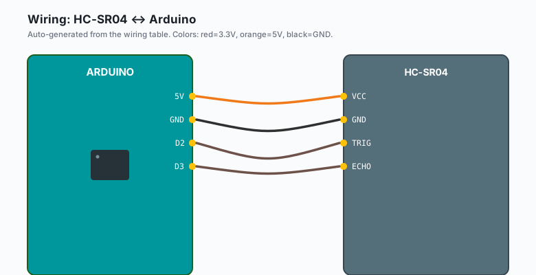
Two circuits share a ground: the logic (Arduino, sensor, servo) and the power (battery, L298N). The battery must not feed the Arduino’s 5V pin; the L298N’s onboard regulator handles the 5V rail.
| HC-SR04 | Arduino |
|---|---|
VCC | 5V |
GND | GND |
TRIG | D2 |
ECHO | D3 |
| SG90 servo | Arduino |
|---|---|
| Orange (signal) | D9 |
| Red | 5V |
| Brown | GND |
| L298N | Arduino / motors / power |
|---|---|
| IN1 | D5 |
| IN2 | D6 |
| IN3 | D10 |
| IN4 | D11 |
| ENA, ENB | Jumpers on (full speed) for the first run |
| Motor A (OUT1/OUT2) | Left motor |
| Motor B (OUT3/OUT4) | Right motor |
| +12V terminal | 7.4V battery pack |
GND terminal | Battery GND and Arduino GND (common ground, always) |
Power the Arduino from the L298N’s 5V output or from USB during bench testing, never from both at once. USB plus an external 5V feed fight each other through the Arduino’s regulator.
Mount the HC-SR04 on the servo horn at the front of the chassis, facing forward, high enough that the sensor beam clears the wheels. Servo centered should point straight ahead.
Install
No libraries needed for this build. The HC-SR04 runs on raw
pulseIn() timing (the same one-formula approach from the ultrasonic
tutorial) and the servo runs on Servo.h, which ships with the
Arduino IDE already. Nothing to install from
Arduino IDE >> Sketch >> Include Library >> Manage Libraries, which
is one less thing to break on a moving robot.
The code
#include <Servo.h>

const int TRIG = 2, ECHO = 3;
const int SERVO = 9;
const int IN1 = 5, IN2 = 6, IN3 = 10, IN4 = 11;
const int OBSTACLE_CM = 25;

Servo scan;

int pingCm(int angle) {
  scan.write(angle);        // point the sensor
  delay(150);               // let the servo settle
  digitalWrite(TRIG, LOW);  delayMicroseconds(2);
  digitalWrite(TRIG, HIGH); delayMicroseconds(10);
  digitalWrite(TRIG, LOW);
  long t = pulseIn(ECHO, HIGH, 30000);   // 30 ms timeout
  return t ? t / 29 / 2 : 300;           // no echo = treat as far
}

void drive(int l, int r) {   // l,r: +1 forward, -1 back, 0 stop
  digitalWrite(IN1, l > 0); digitalWrite(IN2, l < 0);
  digitalWrite(IN3, r > 0); digitalWrite(IN4, r < 0);
}

void setup() {
  pinMode(TRIG, OUTPUT); pinMode(ECHO, INPUT);
  pinMode(IN1, OUTPUT); pinMode(IN2, OUTPUT);
  pinMode(IN3, OUTPUT); pinMode(IN4, OUTPUT);
  scan.attach(SERVO);
  scan.write(90);           // center
  delay(500);
}

void loop() {
  int ahead = pingCm(90);
  if (ahead > OBSTACLE_CM) { drive(1, 1); return; }   // clear: go

  drive(0, 0);                        // stop and look around
  int left  = pingCm(160);
  int right = pingCm(20);

  if (left > right && left > OBSTACLE_CM) {           // more room left
    drive(-1, 1); delay(400); drive(0, 0);            // spin left
  } else if (right > OBSTACLE_CM) {
    drive(1, -1); delay(400); drive(0, 0);            // spin right
  } else {
    drive(-1, -1); delay(500); drive(0, 0);           // boxed in: back up
  }
  scan.write(90);
  delay(100);
}
The 300 fallback when pulseIn times out is a design decision, not
a shortcut: a sensor pointed at a soft object (a curtain, a couch
cushion) returns no echo because ultrasound is absorbed, not
reflected. Treating “no echo” as “clear” keeps the robot moving in
the exact situation where a naive build freezes. (e.g. pointing the
sensor at a pillow reads 300 cm every time; that is the sound being
eaten, not the sensor failing.)
What you learned
- Sweeping one sensor beats staring forward with it: two measurements give the robot a choice, and choosing is navigation.
- The L298N’s motor supply and the Arduino’s logic supply are separate circuits with one shared ground.
pulseIntimeouts are error handling: no echo is data, and deciding what it means is the actual programming job.
When something breaks
- Robot twitches, motors hum, nothing moves: battery voltage under 7V. The L298N eats about 2V of the supply as dropout, and 4x AA (6V) is not enough. Two 18650s (7.4V) fix it.
- Robot drives backward forever: one motor wired backwards. Every TT motor polarity is arbitrary until you test it. Run the robot with wheels off the ground, confirm both spin forward on “forward”, and flip whichever motor’s leads are wrong.
- Sensor reads fine on the desk, garbage on the robot: the servo’s current draw browns out the 5V rail during sweeps. Add a 470 uF capacitor across the servo’s power leads, or power the servo from a separate 5V buck with common ground.
- Robot avoids walls but clips table legs: thin obstacles
(chair legs, table edges) barely reflect ultrasound at a grazing
angle. Slow down: turn the ENA/ENB jumpers into PWM speed control
at about 180/255 and give the sensor more settle time in
pingCm. - Resets when motors start: brownout from motor inrush on a shared power path. Keep the Arduino fed from its own regulator path and add a 100-470 uF capacitor across the L298N’s 5V rail.
What to build next
- The line-following robot is the same chassis and driver with the sensing problem inverted: instead of avoiding what is there, follow what is.
- The ESP32 robot base tutorial is this exact chassis on Wi-Fi, driven from a web page instead of flying solo.
- Pair the L298N tutorial with the servo tutorial if you want the motor and sensor halves of this build explained in isolation first.
- The 8x8 LED matrix makes a decent rear-facing mood display for a robot that backs up a lot.
The Arduino Robotics book collects the robot projects (line follower, this one, the arm) as chapters that build on each other.