Arduino: long-range 2.4 GHz radio links with nRF24L01
Two Arduinos talking over 2.4 GHz with nRF24L01 modules, no WiFi, no phone, one capacitor and a library. Sensor links that run for months.
WiFi needs an access point. Bluetooth needs a phone. Sometimes you just want two boxes in different rooms to exchange a few numbers (e.g. the mailbox tells the house it has mail, the garage reports its temperature). That job belongs to the nRF24L01: a $2 module that speaks 2.4 GHz point-to-point, draws microamps asleep, and runs for months on a pair of AA batteries when you let the Arduino sleep too.
This tutorial wires two Arduinos, one transmitter (reads a sensor, sends a packet every 5 seconds) and one receiver (prints packets and confirms them), over the RF24 library. The pattern is the backbone of every battery-powered sensor node I have built.
The trap first, because it eats everyone: the nRF24L01 is a 3.3V chip that needs clean, close power, and it fails in a very specific dishonest way. With a marginal supply it still initializes, still answers radio-detail commands, prints its registers happily… and never actually transmits or receives. I burned two evenings on a “code problem” that was a breadboard’s flaky 3.3V rail. If your modules pass the check-radio test but no packet ever arrives, do not debug the code. Fix the power first: capacitor directly on the module’s own VCC/GND pins, and never trust a breadboard’s 3.3V rail for radio work.
What you need
Needed
- 2x Arduino Uno (a Nano for the sensor node is better: smaller board, same code)
- 2x nRF24L01+ modules (the standard 2x4-pin-header PCB antenna type, about $2 each; the version with the SMA antenna and PA/LNA stage reaches much further, about $8)
- 2x 10-100 uF electrolytic capacitor (one across each module’s VCC and GND, right at the module)
- Breadboard and jumper wires
- One sensor for the transmitter (e.g. an LDR on A0, or reuse the DHT22 wiring from its tutorial)
- 2x 18650 battery packs if the sensor node will live untethered
Why nRF24L01+ over ESP8266-for-WiFi: zero infrastructure, microamp sleep, and the packets land at both ends with automatic acknowledgement. Over WiFi the same job costs a router, a client stack, and two orders of magnitude more sleep current.
Nice to have
- Multimeter (measuring the module’s VCC under load is how you diagnose the power trap)
- Soldering iron and solder (the header pins on cheap modules are push-fit at best; a solder joint ends years of intermittent contact)
- Iron stand and helping hands
- Wire stripper
- Anti-static wristband (these modules are genuinely static sensitive)
- Magnifying goggles (the silkscreen pin labels are 2 mm tall)
Wiring
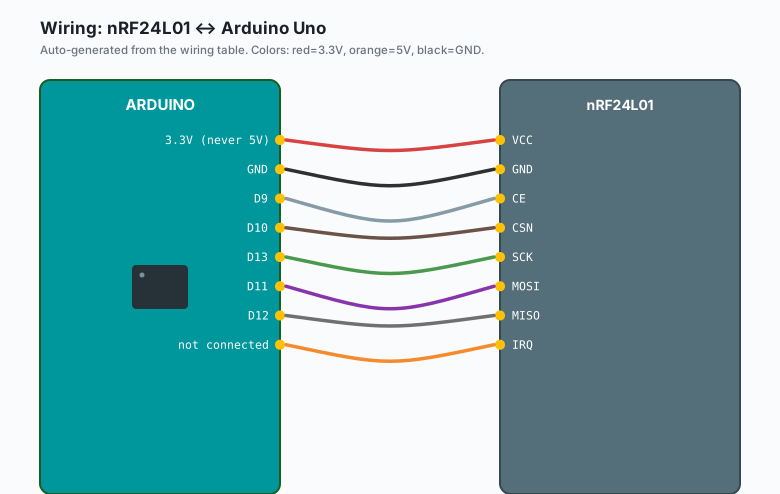
| nRF24L01 | Arduino Uno |
|---|---|
VCC | 3.3V (never 5V) |
GND | GND |
| CE | D9 |
| CSN | D10 |
SCK | D13 |
MOSI | D11 |
MISO | D12 |
IRQ | not connected |
Pin 1 of the module is the one with the square pad on the silkscreen, and it is VCC. The 2x4 header counts down one side and back the other; the connector is asymmetric enough that forcing it backwards is possible, and backwards means GND on VCC and a dead module. Check twice.
The capacitor goes across the module’s VCC and GND pins at the module, not at the breadboard rail. Lead length matters: 10 cm of wire between capacitor and module is too far (this is why modules with the capacitor already mounted on a small adapter board are worth the extra dollar).
The SPI pins (D11-D13) are fixed on the Uno. If you also drive an LED from D13, that is the SPI clock now; move the LED.
Install
Sketch >> Include Library >> Manage Libraries >> search “RF24” by TMRh20 >> Install (both machines).
RF24 by TMRh20, not the old ManiacBug RF24, is the maintained lineage. The API is the same; the TMRh20 fork fixes years of bugs and supports the PA/LNA variants properly.
The code
Two sketches. Same RF24 library, mirrored roles.
Transmitter (sensor node):
// TX: read a sensor, send a packet every 5 s, blink on ack.
#include <SPI.h>
#include <nRF24L01.h>
#include <RF24.h>

RF24 radio(9, 10);  // CE, CSN

const byte ADDRESS[6] = "NODE1";
const int SENSOR = A0;
const int LED = 7;

struct Packet {
  uint32_t seq;
  int value;
};

Packet pkt;
uint32_t seq = 0;

void setup() {
  pinMode(LED, OUTPUT);
  radio.begin();
  radio.setChannel(108);            // above WiFi channel 1 clutter
  radio.setPALevel(RF24_PA_LOW);    // start low; raise only with good power
  radio.openWritingPipe(ADDRESS);
  radio.stopListening();            // transmitter only
  Serial.begin(9600);
}

void loop() {
  pkt.seq = seq++;
  pkt.value = analogRead(SENSOR);

  bool ok = radio.write(&pkt, sizeof(Packet));

  Serial.print(pkt.seq);
  Serial.print(" v=");
  Serial.print(pkt.value);
  Serial.println(ok ? "  ack" : "  no ack");

  digitalWrite(LED, ok);            // solid LED means the link is alive
  delay(5000);
}
Receiver (base station):
// RX: listen on NODE1, print every packet.
#include <SPI.h>
#include <nRF24L01.h>
#include <RF24.h>

RF24 radio(9, 10);  // CE, CSN

const byte ADDRESS[6] = "NODE1";
const int LED = 7;

struct Packet {
  uint32_t seq;
  int value;
};

Packet pkt;

void setup() {
  pinMode(LED, OUTPUT);
  radio.begin();
  radio.setChannel(108);
  radio.setPALevel(RF24_PA_LOW);
  radio.openReadingPipe(0, ADDRESS);
  radio.startListening();           // receiver only
  Serial.begin(9600);
}

void loop() {
  if (radio.available()) {
    radio.read(&pkt, sizeof(Packet));
    Serial.print("node ");
    Serial.print(pkt.seq);
    Serial.print(" value ");
    Serial.println(pkt.value);
    digitalWrite(LED, HIGH);
    delay(20);
    digitalWrite(LED, LOW);
  }
}
Notes on the choices, because each one is load-bearing:
setPALevel(RF24_PA_LOW)first. The MAX setting draws peak currents the Uno’s 3.3V regulator barely supplies, and a marginal supply produces the exact “everything works but no packets” failure this tutorial opened with. Raise power only after the link is proven, with the capacitor in place.- The struct, not a bare int, is the pattern that scales: add a battery voltage field to the struct and both ends agree automatically (same struct definition on both sides, or the packets misparse).
- The ack LED closes the loop: solid means packets are landing, blinking means retries. You can see the link quality from across the room.
What you learned
- SPI radio wiring: CE and CSN are your two ordinary GPIOs, the rest ride the hardware SPI bus. Same layout as every SPI device on this site (the SD logger, the RFID reader).
- Automatic acknowledgement is built in: radio.write returns true only when the receiver confirmed. That single boolean is your link monitor.
- Address pipes (up to 6 on one receiver) are how you grow from one sensor node to a small sensor network: one base, many transmitters, each with its own pipe address.
When something breaks
- radio.begin() fails or prints “radio hardware is not responding”. Wiring first: MISO/MOSI swapped is the classic, then CSN/CE. Then power: 5V on VCC kills the module outright.
- Checks pass, but no packets ever arrive (the big one). Power rail. Add the capacitor at the module, move both modules off the breadboard rails, drop PA level to LOW. If a wall outlet USB charger is powering the receiver, try a different supply; some are too noisy for radio work.
- Works on the desk, fails across the room. You raised the PA level without fixing the power, or you are in a room with a WiFi router at channel 1-6. Change setChannel (108 works; anything in 125 down to about 70 sits above most WiFi), or accept the drop and add retry tuning (setRetries(5, 15)).
- Packets arrive with garbage values. Struct mismatch: the two sketches have different struct definitions (field order or types). Copy the struct into a header or paste it byte-for-byte into both. Padding differences between AVR and other boards can do the same thing; keep the struct to same-size fields.
- Range is 10 meters when the listing said 100. The stock PCB antenna module is honest about its range: 20-30 m outdoors, less through walls. The PA/LNA version with the external antenna is the honest 100 m part. Antennas on both ends must match in expectations, and keep the module’s PCB antenna clear of metal and of the Arduino body itself.
What to build next
- A three-node sensor network: the receiver opens three reading pipes (openReadingPipe(1..3)) and one base station collects from a mailbox node, a garden node, and a garage node. The struct from this tutorial is the per-node payload.
- The obstacle-avoiding robot pair: put an nRF24 on the robot and a nunchuck-style controller board in your hand (the same two-Arduino link, one direction, small packets, 50 Hz).
- The line-follower robot and this tutorial together make a telemetry rover: the robot drives the tape, the radio streams sensor values to a base station on your desk while it runs.