Arduino: build a digital clock with DS3231 + OLED
Build a desk clock that never drifts: a DS3231 RTC keeps time, a 0.96 inch SSD1306 OLED shows it big. Two I2C devices on the same two wires, plus a button to set it.
The desk clock is the project that makes other people ask about your hobby. It is also the natural endpoint of two tutorials: the DS3231 RTC tutorial (the clock chip) and the 16x2 LCD tutorial (the “print something to a screen” skill). This one combines them: a DS3231 for the time and a 0.96” SSD1306 OLED for the display, both hanging off the same two I2C wires. Big digits, accurate to two minutes a year, and it survives an unplug.
The trap I hit: my first version called display.clearDisplay() and
display.display() on every loop iteration, thousands of times per
second. The result was shimmering text and a flicker you can see from
across the room (and a chip working much harder than needed). Redraw
the screen only when the second actually changes, and the display is
rock steady.
What you need
Needed
- Arduino Uno (or Nano): the board
- DS3231 RTC module (ZS-042 breakout, about $3): the timekeeper; the OLED clock tutorial needs this plus the coin cell to keep time through power cycles
- 0.96” OLED display, SSD1306 driver, I2C version (about $4; the 4-pin one: VCC, GND, SCL, SDA): the screen. Do not buy the SPI version for this project, it needs more wires and a different library
- CR2032 coin cell for the RTC module: keeps the time when USB is out
- 6x jumper wires: both devices share the same two I2C lines
- One momentary pushbutton: the “set mode” trigger
- Breadboard: two I2C devices means a shared rail, which is what the breadboard is for
Nice to have
- Soldering iron + solder: if the OLED or RTC module shipped with an unsoldered header
- Helping hands: keeps the header at 90 degrees while you solder
- Soldering mat + iron stand: the workshop layer for that job
- Multimeter: to meter the coin cell when the clock starts losing time
- Wire stripper: for making the shared I2C rail tidy
- Anti-static wristband: the OLED glass does not love static
- Magnifying goggles: the OLED’s pin labels are tiny
Wiring
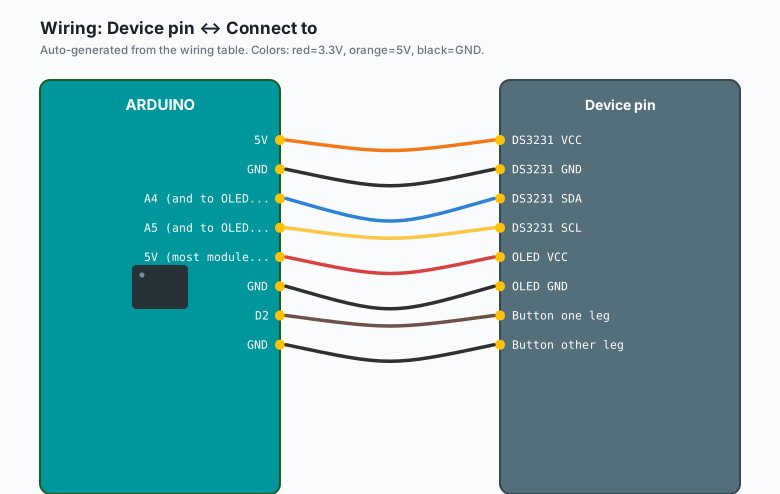
Two I2C devices, one bus. Everything is parallel:
| Device pin | Connect to |
|---|---|
DS3231 VCC | 5V |
DS3231 GND | GND |
DS3231 SDA | A4 (and to OLED SDA) |
DS3231 SCL | A5 (and to OLED SCL) |
OLED VCC | 5V (most modules have a 3.3V regulator onboard) |
OLED GND | GND |
| Button one leg | D2 |
| Button other leg | GND |
Both devices on the same bus is the entire point of I2C: different addresses (RTC is 0x68, OLED is 0x3C or 0x3D), shared wires. If the OLED shows nothing, run the I2C scanner from the I2C tutorial and confirm you actually have 0x68 and 0x3C on the bus before changing any code.
Install
Arduino IDE >> Sketch >> Include Library >> Manage Libraries, and install two libraries:
- “Adafruit SSD1306” (with its dependency “Adafruit GFX Library”, which the Library Manager offers to install alongside)
- “RTClib” by Adafruit
The code
The set-time step first, because a clock with no time is just a dark
glass rectangle. Upload the RTC tutorial’s set sketch once (the one
with rtc.adjust(DateTime(F(__DATE__), F(__TIME__)))), then continue
with this main sketch, which never touches the time unless you hold
the button.
#include <Wire.h>
#include <RTClib.h>
#include <Adafruit_GFX.h>
#include <Adafruit_SSD1306.h>

RTC_DS3231 rtc;

#define SCREEN_WIDTH 128
#define SCREEN_HEIGHT 64
Adafruit_SSD1306 display(SCREEN_WIDTH, SCREEN_HEIGHT, &Wire, -1);

const int BUTTON_PIN = 2;      // button to GND, INPUT_PULLUP
const unsigned long HOLD_MS = 2000;   // hold 2 s to enter set mode

// Set mode state
bool inSetMode = false;
int setField = 0;              // 0=hour, 1=minute
DateTime editing;

void setup() {
  Serial.begin(57600);
  pinMode(BUTTON_PIN, INPUT_PULLUP);

  if (!rtc.begin()) {
    Serial.println("No RTC found.");
    while (true) delay(10);
  }
  if (rtc.lostPower()) {
    // First boot or dead battery: fall back to compile time, then
    // use the button to fix it properly.
    rtc.adjust(DateTime(F(__DATE__), F(__TIME__)));
  }

  if (!display.begin(SSD1306_SWITCHCAPVCC, 0x3C)) {
    Serial.println("OLED not found at 0x3C. Try 0x3D.");
    while (true) delay(10);
  }
  display.clearDisplay();
  display.setTextColor(SSD1306_WHITE);
}

void drawClock(const DateTime& now, bool blinkColon) {
  display.clearDisplay();
  display.setTextSize(3);                     // big digits
  display.setCursor(8, 20);
  if (now.hour() < 10) display.print('0');
  display.print(now.hour());
  if (blinkColon) display.print(':'); else display.print(' ');
  if (now.minute() < 10) display.print('0');
  display.print(now.minute());
  display.setTextSize(1);
  display.setCursor(0, 0);
  char buf[12];
  now.toString(buf);           // "YYYY-MM-DD HH:MM:SS"
  display.print(buf + 5);      // skip year: MM-DD HH:MM:SS
  display.setCursor(0, 56);
  display.print(inSetMode ? "SET: " : "");
  display.display();
}

bool buttonHeld() {
  static unsigned long pressStart = 0;
  if (digitalRead(BUTTON_PIN) == LOW) {
    if (pressStart == 0) pressStart = millis();
    if (millis() - pressStart >= HOLD_MS) return true;
  } else {
    pressStart = 0;
  }
  return false;
}

bool buttonClicked() {
  static unsigned long lastRelease = 0;
  static bool wasPressed = false;
  bool pressed = (digitalRead(BUTTON_PIN) == LOW);
  bool clicked = false;
  if (!pressed && wasPressed && millis() - lastRelease > 50) {
    clicked = true;
  }
  if (!pressed && wasPressed) lastRelease = millis();
  wasPressed = pressed;
  return clicked;
}

void loop() {
  static int lastSecond = -1;
  DateTime now = rtc.now();

  if (inSetMode) {
    if (buttonHeld()) {                        // hold again: save and exit
      rtc.adjust(editing);
      inSetMode = false;
    } else if (buttonClicked()) {
      setField = (setField + 1) % 2;           // toggle hour/minute
      if (setField == 0) {
        editing = editing + TimeSpan(0, 1, 0, 0);   // +1 hour
      } else {
        editing = editing + TimeSpan(0, 0, 1, 0);   // +1 minute
      }
    }
    drawClock(editing, true);
    delay(50);
    return;
  }

  // Normal clock mode: redraw only when the second changes
  if (now.second() != lastSecond) {
    lastSecond = now.second();
    drawClock(now, (now.second() % 2) == 0);
  }

  if (buttonHeld()) {
    editing = now;
    setField = 0;
    inSetMode = true;
    delay(300);                 // debounce before set mode starts
  }
}
The pattern to take away: redraw on change, not on loop. now.second() != lastSecond means the screen updates once per second and stays
still the other 15 million loop iterations. That single check is the
difference between a clock that shimmers and one you can read across
the room.
The set flow: hold the button 2 seconds to enter set mode (the clock freezes on the editing time), click to add an hour or a minute (alternating), hold again to save. Not fancy, but it needs one button and it works (e.g. the “hold to enter, click to change, hold to save” pattern is the same one cheap kitchen timers use).
Variations worth 10 minutes each
- 24h vs 12h: the RTC stores 24-hour time. To display 12-hour, subtract 12 from hours above 12 and print “PM”. Keep the RTC in 24h and do the conversion only at draw time.
- Temperature line: the DS3231 measures its own temperature (the
crystal compensation sensor).
rtc.getTemperature()gives you a bonus data line for row 2 of the display. - Night dimming: OLEDs have no analog dim, but you can fake it by
drawing in dark gray (
SSD1306_DIMMODEstyle contrast viadisplay.dim(true)), which drops brightness for late-night desks.
What you learned
- Two I2C devices share two wires when their addresses differ; the scanner confirms both before you debug anything else.
- Redraw-on-change is the OLED pattern that fixes flicker (check a value, update the screen only when it moved).
- The DS3231 does the timekeeping; the Arduino only formats and displays. That division of labor is the whole architecture.
When something breaks
- Nothing on the OLED: 90% of the time the display is at address
0x3D or the I2C wires are swapped. Run the scanner (I2C tutorial),
use the address it reports in
display.begin(..., 0x3C). - Everything works until you unplug: the coin cell is dead or the module’s charge circuit is fighting it. Meter the cell (3.0 V+ healthy) and check the RTC tutorial’s note on LIR2032 vs CR2032.
- Clock shows the wrong fixed time after every re-upload: a
compile-time
rtc.adjust()is still in the code. It runs on every boot. Gate it behindlostPower()(as the sketch above does) or delete the line. - Flicker or shimmer on the text: you are calling
display()every loop, or sharing a breadboard rail so thin the OLED browns out. Redraw on change (as above), and feed the OLED’s VCC directly from the Arduino 5V pin, not from a distant breadboard row. - Time is right but date is off by a day: the module’s day-of-week
register was never set (it starts at 1 on a fresh chip).
toString()shows what the chip holds; set the full DateTime once with the button flow and it stays put.
What to build next
- The EEPROM tutorial saves your preferred display mode (24h or 12h, dim or bright) so it survives a power cycle.
- The night security light tutorial is the same “RTC decides when” architecture driving a relay instead of a screen.
- The traffic light tutorial turns the clock into a school crossing light: walk signal on a schedule from the RTC alarm.