Arduino: electronic dice roller with 7-segment display
Roll a die with a button press: a 7-segment display shows 1 to 6 with a tumble animation. Direct-drive wiring, a segment map, and honest randomness on the Uno.
The electronic dice roller is the project I build with people right after blink, because it smuggles in four real lessons at once: driving a 7-segment display, debouncing a button, generating randomness that is not obviously fake, and pacing a “spin down” animation that makes the thing feel like a product instead of a demo. One button, one display, one resistor pack, about an hour.
The trap I hit: I wired the display’s segments to Arduino pins in the order the pins appear on the part (a, b, c, d, e, f, g, dp to pins 2 through 9) and then my digit “8” came out as a backwards “S”. The segments were fine; my wiring table did not match my segment constants. Wire in one deliberate order, write that order in the table at the top of the sketch, and never “fix” a wrong digit by re-ordering the array (e.g. fix it at the wiring step, once).
What you need
Needed
- Arduino Uno (or Nano): the board
- 1-digit 7-segment display, common cathode (the standard 5161AS, about $1): the display; common cathode keeps the logic simple (segment pin HIGH = lit). Common anode works too, just invert everything
- 7x 220 ohm resistors: one per segment (yes, seven; a single shared resistor makes digits dim unevenly because segments carry different current)
- One momentary pushbutton: the roll button
- 9x jumper wires + breadboard: the segment runs
Nice to have
- A 2-digit or 4-digit 7-segment display: for two-dice mode later
- Wire stripper + helping hands: tidiest wiring job of the beginner projects, worth the five minutes
- Multimeter: to identify which pin is which segment on an unmarked display (3V coin cell + 1k resistor, touch pins, watch what lights)
- Soldering iron + solder: only if you bought bare displays without header pins
- Soldering mat + iron stand: the usual workshop layer for that
- Magnifying goggles: the segment letters are printed tiny on the underside, if at all
Wiring
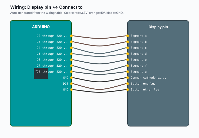
| Display pin | Connect to |
|---|---|
| Segment a | D2 through 220 ohm |
| Segment b | D3 through 220 ohm |
| Segment c | D4 through 220 ohm |
| Segment d | D5 through 220 ohm |
| Segment e | D6 through 220 ohm |
| Segment f | D7 through 220 ohm |
| Segment g | D8 through 220 ohm |
| Common cathode pins (the 2 middle pins) | GND |
| Button one leg | D10 |
| Button other leg | GND |
The two middle pins on a 1-digit display are both the common cathode; connect either one (they are the same pin internally). On an unmarked display, segments map like this: hold the display with the decimal point at the bottom right, then top=a, top-right=b, bottom-right=c, bottom=d, bottom-left=e, top-left=f, middle=g.
Install
Nothing to install. This project uses no libraries at all: the display is driven directly with digitalWrite(), which is the point. (When you move to 4-digit displays, a library like SevSeg earns its keep; for one digit, raw pins are clearer.)
The code
// Segment-to-pin map. This matches the wiring table above exactly.
const int SEG[7] = {2, 3, 4, 5, 6, 7, 8};   // a b c d e f g
const int BUTTON = 10;

// Digit patterns: bit 0 = a, bit 1 = b, ... bit 6 = g.
// 1 = segment on (common cathode).
const byte DIGITS[10] = {
  0b0111111,   // 0: a b c d e f
  0b0000110,   // 1: b c
  0b1011011,   // 2: a b d e g
  0b1001111,   // 3: a b c d g
  0b1100110,   // 4: b c f g
  0b1101101,   // 5: a c d f g
  0b1111101,   // 6: a c d e f g
  0b0000111,   // 7: a b c
  0b1111111,   // 8: all
  0b1101111    // 9: a b c d f g
};

void showDigit(byte d) {
  byte pattern = DIGITS[d];
  for (int seg = 0; seg < 7; seg++) {
    digitalWrite(SEG[seg], (pattern >> seg) & 1);
  }
}

void clearDisplay() {
  for (int seg = 0; seg < 7; seg++) digitalWrite(SEG[seg], LOW);
}

// A face worth of pixels is overkill; dice faces 1-6 on a 7-segment
// display look best as the actual numerals. This animation instead
// flashes cycling numbers that slow down, like a slot machine.
void rollAnimation() {
  // Tumble fast, then slow down: 30 steps of increasing delay.
  int delayMs = 20;
  for (int step = 0; step < 30; step++) {
    showDigit(random(1, 7));      // 1..6
    delay(delayMs);
    delayMs += 8;                 // 20, 28, 36 ... 250ish at the end
  }
}

void setup() {
  for (int i = 0; i < 7; i++) pinMode(SEG[i], OUTPUT);
  pinMode(BUTTON, INPUT_PULLUP);
  clearDisplay();
  randomSeed(analogRead(A0));     // A0 floating: a different seed every boot
  showDigit(8);                   // power-on self test: all segments
}

void loop() {
  static unsigned long lastRelease = 0;

  // Wait for press
  if (digitalRead(BUTTON) == LOW) {
    delay(30);                     // debounce settle
    if (digitalRead(BUTTON) == LOW) {
      rollAnimation();

      // Fair pick: discard the first draw after the animation,
      // then take one clean random.
      random(1, 7);
      int face = random(1, 7);

      showDigit(face);
      Serial.print("Rolled: ");
      Serial.println(face);

      // Wait for release so one press = one roll
      while (digitalRead(BUTTON) == LOW) { delay(10); }
      lastRelease = millis();
    }
  }
}
Three things worth noticing:
- The segment map lives in one array and the digit patterns are
bitmasks over it. To fix a wired-wrong segment you change the
wiring (per the trap above), not the array. To fix a
designed-wrong digit (my backwards S), you change one row of
DIGITS[], and nothing else. randomSeed(analogRead(A0))reads a floating analog pin, which settles at a different voltage every boot. Without a seed, the Uno produces the identical “random” sequence every reset (e.g. the memory-game tutorial uses the same trick, and the same honesty note: this is unseeded-enough for games, not for cryptography).- The spin-down animation is a loop with a growing delay. The display shows real tumbling faces the whole time, and the final face is drawn once the tumble ends. The delay ramp (20 ms up to ~250 ms) is the whole “slot machine” feel.
Two-dice mode (the natural extension)
Two dice need either two displays (wire the second the same way and show both faces) or the trick version: one display showing one die, then the other, alternating fast enough that both appear lit. That is multiplexing, the same trick the MAX7219 does in hardware. Try it with two displays first (e.g. 14 segments direct-driven, still fits the Uno’s pin budget with the button on A1 as a digital pin).
What you learned
- A 7-segment digit is just a map from numbers to which segments to light; the bitmask array is the entire display driver.
randomSeed(analogRead(A0))plus a discard draw gets you dice that do not repeat the same sequence every reset.- Spin-down pacing (growing delays) turns an instant answer into a moment of suspense. Interface feel is code, not hardware.
When something breaks
- Digit looks wrong (backwards S instead of 8): one or more
segments are mapped to the wrong pins. Compare the wiring table to
SEG[]and light each segment one at a time with a test loop to find the mismatch. - Some segments dimmer than others: you used one resistor for the whole display (shared common) instead of one per segment. Each segment needs its own 220 ohm resistor on this wiring.
- Button rolls multiple dice per press: the wait-for-release loop is missing, or the debounce delay is too short for a really bouncy button. Bump the settle to 50 ms and keep the release wait.
- Same sequence of numbers every reset: the seed line is missing (or A0 is tied to something fixed, like a sensor rail). A floating A0 + randomSeed is the fix.
- Display completely dark: you have a common-anode display (the
common pins go to 5V, not GND) with common-cathode code. Either
swap the common to 5V and invert every pattern with
~pattern, or buy the 5161AS (cathode) the parts list names.
What to build next
- The memory game tutorial shares the button-plus-display core; swap the die for a Simon sequence and you already know the parts.
- The 8x8 LED matrix tutorial is the same idea with 64 pixels of freedom: dice pips as an actual dot pattern instead of a numeral.
- The EEPROM tutorial stores a running win count so the dice remember your roll history across power cycles (e.g. a “luckiest roll today” scoreboard).