Arduino: control it from an Android app with MIT App Inventor
Drive an Arduino over Bluetooth from an Android app you build yourself with MIT App Inventor, no Java, one HC-06 module, two-way control.
An Arduino on your desk is a demo. An Arduino you can drive from your phone is a robot. The bridge is old, cheap, and everywhere: an HC-06 Bluetooth-to-serial module that makes your Arduino look like a serial port to Android, and MIT App Inventor, the drag-and-drop tool that builds a real installable Android app in a browser without a line of Java (e.g. the app in this tutorial is about a dozen blocks long).
You will build both halves: the Arduino sketch that listens for commands (L1, L0, a lamp on and off) and sends sensor readings back, plus the App Inventor app with buttons, a picker, and a label that shows the reply. The same pattern scales to a robot car, a curtain motor, or a chicken-coop door.
The trap first: HC-06 means Bluetooth Classic, not Bluetooth LE. Modern iPhones cannot talk to it at all, and many Android phones hide it behind a permission. I built the first version of this project, handed my phone to someone with an iPhone, and watched nothing happen while both of us assumed the other was holding it wrong. Android only, Bluetooth Classic only. If you need iPhone or desktop support, that is the ESP32 BLE tutorial territory, and the code is a different shape. Say it now so the next hour is not a mystery.
What you need
Needed
- Arduino Uno (or Nano, same code)
- HC-06 Bluetooth module (about $4; HC-05 also works, it has more pins and does master mode you will not use here)
- Android phone (Android 5 or newer; the Companion app needs a Google account-free install in most cases)
- 4x jumper wires
- One output to control: an LED on D13 for the demo, or the relay module if you want to switch something real
- A computer with a browser, for the App Inventor side (ai2.appinventor.mit.edu, free, MIT account login)
Why HC-06 over BLE modules: it is a transparent serial pipe. The Arduino code is just Serial. No Bluetooth library, no GATT, no notifications. For phone-to-Arduino command links that is exactly the right amount of technology.
Nice to have
- Multimeter (checking the divider you are about to build)
- Wire stripper
- Anti-static wristband (the HC-06 is a bare PCB, treat it like one)
- Helping hands (holding the module while you jumper it)
- Second phone or a friend’s phone (pairing is per-phone; testing on two phones catches the pairing-mode trap early)
Wiring
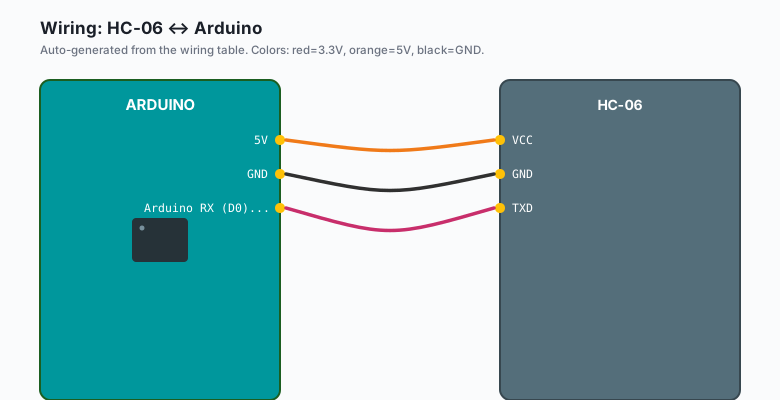
The HC-06 runs on 3.3V logic. Its RX pin is not 5V tolerant, and that is the one wiring detail that matters here.
| HC-06 | Arduino |
|---|---|
VCC | 5V |
GND | GND |
TXD | Arduino RX (D0) for the simple version, or D2 for SoftwareSerial |
RXD | through a voltage divider (1k from D3, 2k to GND, tap to RXD) |
| Relay (optional) | Arduino |
|---|---|
VCC | 5V |
GND | GND |
| IN | D8 |
Two ways to connect the module, pick one:
- The easy way: remove the sketch from the Uno, wire TXD to D0 and RXD to the divider from D1, and let the hardware UART talk. Downside: you cannot print debug output while Bluetooth is on those pins, and uploading a new sketch fails while the module holds D0/D1.
- The better way (used in the code below): SoftwareSerial on D2/D3. The hardware serial stays on USB for debugging, the Bluetooth lives on two other pins, and the divider protects the module’s RX.
The divider: Arduino TX (D3) is 5V, the HC-06 RX wants 3.3V. A 1k resistor in series and a 2k resistor to ground gives 5 x (2/3) = 3.33V. The module’s TX at 3.3V already reads fine as 5V logic on the Arduino side, no divider needed that direction.
Power the HC-06 from 5V on VCC (the board has its own regulator) but never feed 5V into RXD. The divider is not decoration. I have killed an HC-06 exactly once, and it was exactly this.
Install
Nothing to install on the Arduino side: SoftwareSerial ships with the IDE.
On the phone:
- Pair first, before opening any app: Settings >> Connected devices >> Pair new device, PIN is 1234 (some modules use 0001 or 0000; the HC-06 default is 1234).
- On the computer: sign in at ai2.appinventor.mit.edu, start a new project called ArduinoBt.
- On the phone: install “MIT AI2 Companion” from the Play Store and test live over your Wi-Fi, or use Build >> Android App (.apk) and install the apk directly.
The code
// Bluetooth control: SoftwareSerial on D2/D3, LED on D13, relay on D8.
// Phone sends 'L1' or 'L0'; Arduino replies with a status line.

#include <SoftwareSerial.h>

SoftwareSerial BT(2, 3);  // RX, TX (RX is where the module talks to us)

const int LED   = 13;
const int RELAY = 8;
const int SENSOR = A0;    // something to send back (e.g. an LDR)

char buf[8];
byte idx = 0;

void setup() {
  pinMode(LED, OUTPUT);
  pinMode(RELAY, OUTPUT);
  BT.begin(9600);          // HC-06 default baud
  Serial.begin(9600);
  BT.println("READY");
}

void loop() {
  while (BT.available()) {
    char c = BT.read();
    if (c == '\n' || c == '\r') {
      buf[idx] = '\0';
      if (idx > 0) handle(buf);
      idx = 0;
    } else if (idx < 7) {
      buf[idx++] = c;
    }
  }
}

void handle(char *cmd) {
  Serial.print("cmd: ");
  Serial.println(cmd);

  if (strcmp(cmd, "L1") == 0) {
    digitalWrite(LED, HIGH);
    digitalWrite(RELAY, HIGH);
    BT.println("LAMP ON");
  } else if (strcmp(cmd, "L0") == 0) {
    digitalWrite(LED, LOW);
    digitalWrite(RELAY, LOW);
    BT.println("LAMP OFF");
  } else if (strcmp(cmd, "S?") == 0) {
    int v = analogRead(SENSOR);
    BT.print("SENSOR ");
    BT.println(v);
  } else {
    BT.println("ERR");
  }
}
The protocol is deliberately dumb: short ASCII lines, one command per line, newline-terminated. Text beats binary here because you can debug it from a plain serial terminal (unplug the module, wire D2/D3 to a USB-serial adapter, and the phone app and the terminal see the same thing). Keep it dumb until you have a reason not to.
The app (App Inventor side)
Designer screen, five components:
- ListPicker (BluetoothPicker): text “Connect”.
- Button (BtnOn): text “Lamp ON”, background green.
- Button (BtnOff): text “Lamp OFF”, background red.
- Button (BtnAsk): text “Read sensor”.
- Label (Status): text empty, the reply shows here.
Plus two non-visible components from the Connectivity palette: Bluetooth and Clock (1000 ms timer).
Blocks (the whole app):
- BluetoothPicker.BeforePicking: set Bluetooth.AddressList to Bluetooth.AddressesAndNames.
- BluetoothPicker.AfterPicking: call Bluetooth.Connect with address = BluetoothPicker.Selection.
- BtnOn.Click: call Bluetooth.SendText with “L1\n”.
- BtnOff.Click: call Bluetooth.SendText with “L0\n”.
- BtnAsk.Click: call Bluetooth.SendText with “S?\n”.
- Clock.Timer: if Bluetooth.IsConnected and Bluetooth.BytesAvailable > 0, set Status.Text to Bluetooth.ReceiveText(-1).
Test it: Companion connects over Wi-Fi, Bluetooth still runs on the phone itself. Pick the HC-06 from the picker (it shows as “HC-06” with its MAC), the READY line may land in Status on connect, and the buttons should switch the LED with “LAMP ON” appearing in the label. Send “S?” and the LDR reading shows up.
What you learned
- Bluetooth-to-serial is a transport, not a protocol: the Arduino does not know or care that the bytes came from a phone. Same sketch would work from a laptop serial terminal.
- Line-framing on both ends (byte buffer, newline-delimited commands, short replies) is the smallest reliable two-way protocol. It is the same shape as the nRF24L01 packet pattern and the ESP32 websocket pattern on this site.
- App Inventor’s event blocks (Click, Timer) map one-to-one onto the polling loop you would write in Java, in a tenth of the code.
When something breaks
- The picker shows nothing after tapping Connect. You skipped BeforePicking setting AddressList, or Bluetooth is off on the phone. The pairing also must exist first: Settings >> Connected devices, pair to HC-06 with PIN 1234 before the app ever runs.
- Connects, but every command silently does nothing. RX/TX are swapped between module and sketch (the module’s TXD goes to the Arduino’s RX pin, always crosswise), or the sketch is on SoftwareSerial pins while the app talks to a hardware-UART wiring. Trace it: type into a serial terminal on the Arduino side and confirm what arrives.
- “Error 507: Connection refused” or instant drop. Another app (or a previous Companion session) still owns the serial profile. Kill Bluetooth on the phone and re-enable, or reboot the phone; this clears it nine times out of ten.
- Garbage characters like “YXXX” on connect. Baud mismatch: HC-06 modules default to 9600, but used modules get reconfigured (AT+BAUD4 makes it 19200, AT+BAUD8 makes it 115200). Drop to the AT command mode (power the module alone, LED slow-blink, send AT) and read its baud, then set BT.begin to match.
- The LED never responds but READY printed. You are watching the Serial Monitor, not the phone. Commands come from the app; Serial Monitor is only the echo. Check the phone’s Status label for the reply, and the LED only follows a real L1 arriving.
What to build next
- The nRF24L01 tutorial on this site: when you want two Arduinos to talk to each other without a phone in the middle, that is the radio to reach for.
- The obstacle-avoiding robot: drive the L298N from this app’s four directional buttons (W/A/S/D style commands like F, B, L, R) and you have a phone-controlled rover.
- The relay module tutorial makes the LAMP ON line switch a real device (a lamp, a fan, a pump), with the safety wiring the demo above skips.