Arduino: real timekeeping and alarms with the DS3231 RTC
Give your Arduino a real clock with the DS3231 RTC module. Set the time, read it back, and fire alarms that survive power loss, drift, and reboot.
Every Arduino project that needs to know “what time is it” eventually needs a real clock. The Uno can count milliseconds with millis(), but pull the plug and the count is gone. The DS3231 is a small I2C module with a temperature-compensated crystal (about $3) that keeps time to within 2 minutes per year, runs years on a CR2032 coin cell, and has two hardware alarm clocks built in.
This tutorial covers wiring, setting the time once, reading it in your own sketches, and both alarm modes. When you are done you have the foundation the OLED clock tutorial builds on.
The trap I hit: I set the time, unplugged the Arduino, reconnected it a day later, and the sketch said 2000-01-01 00:00:00. The DS3231 had kept perfect time the whole time. The problem was my code: on every boot I called a “set the compile time” function that reset the chip to the moment the sketch was built. RTC libraries make that mistake one line easy. Only set the time deliberately (e.g. when you replace the battery or move the module), never on every boot.
What you need
Needed
- Arduino Uno (or Nano): the board
- DS3231 RTC module (the ZS-042 red breakout with CR2032 holder, about $3): the clock itself; it includes the backup battery holder, though the battery itself sometimes ships separately
- CR2032 coin cell: backup power so the time survives USB unplug
- 4x jumper wires: I2C plus power
Nice to have
- Multimeter: to check the battery voltage (a DS3231 with a dead backup cell loses time on every power cycle)
- Soldering iron + solder + wire stripper: only if the header pins came loose in the bag
- A second DS3231: they drift slightly differently; comparing two teaches you more than one ever will
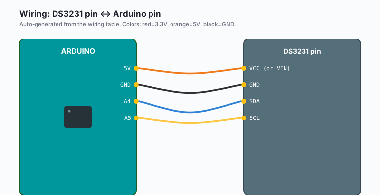
Wiring
Same four wires as every I2C device (the I2C tutorial covers the bus in general):
| DS3231 pin | Arduino pin |
|---|---|
VCC (or VIN) | 5V |
GND | GND |
SDA | A4 |
SCL | A5 |
The ZS-042 board has a charging circuit designed for a LIR2032 (rechargeable) cell. If you use a plain CR2032, check whether your board has the charge resistor populated; many ship with it disconnected. Long term, a CR2032 on a charging board can leak. A LIR2032 costs about a dollar and removes the worry.
Install
Arduino IDE >> Sketch >> Include Library >> Manage Libraries, search “RTClib”, install the one by Adafruit. It drives the DS3231 (and the PCF8523 and DS1307 with the same calls).
The code
First: set the time once, deliberately, with a dedicated sketch.
#include <Wire.h>
#include <RTClib.h>

RTC_DS3231 rtc;

void setup() {
  Serial.begin(57600);
  if (!rtc.begin()) {
    Serial.println("No RTC found. Check wiring.");
    while (true) delay(10);
  }
  // This line sets the RTC to the date & time this sketch was compiled.
  // Run it ONCE. Then comment it out (or use the guard below).
  rtc.adjust(DateTime(F(__DATE__), F(__TIME__)));
  Serial.println("Time set.");
}

void loop() {}
Upload that once, watch “Time set.” appear, then re-upload with the
rtc.adjust(...) line commented out. From now on, the module holds the
time through power cycles, and no boot ever touches it.
A better version of the same idea: only adjust when the RTC lost power.
if (rtc.lostPower()) {
  rtc.adjust(DateTime(F(__DATE__), F(__TIME__)));
}
The DS3231 sets a “lost power” flag when VCC drops while it is running
on the coin cell. lostPower() reads that flag, so the compile-time
backup only fires when the clock actually went dark. Note the residual
error: the time set is the compile time, not the power-on time, so
after a real outage the clock will be off by however long the device
was dead (e.g. re-set it from the Serial Monitor if that matters).
Now the everyday sketch: read and display the time, and use both alarms.
#include <Wire.h>
#include <RTClib.h>

RTC_DS3231 rtc;

const int ALARM1_SQW_PIN = 2;   // SQW pin of the module to D2

volatile bool alarm1Fired = false;

void alarmISR() {
  alarm1Fired = true;
}

void setup() {
  Serial.begin(57600);
  if (!rtc.begin()) {
    Serial.println("No RTC found.");
    while (true) delay(10);
  }

  pinMode(ALARM1_SQW_PIN, INPUT_PULLUP);
  attachInterrupt(digitalPinToInterrupt(ALARM1_SQW_PIN), alarmISR, FALLING);

  // Alarm 1: fire every day at 07:30:00
  rtc.setAlarm1(DateTime(2026, 9, 24, 7, 30, 0), DS3231_A1_Hour);
  // Alarm 2: fire at the top of every minute (seconds match 0)
  rtc.setAlarm2(DateTime(2026, 9, 24, 0, 0, 0), DS3231_A2_Minute);

  rtc.disableAlarm(2);   // we are polling this one, not interrupting

  // Square wave off so the pin does not spam 1 Hz interrupts
  rtc.writeSqwPinMode(DS3231_OFF);
}

void loop() {
  DateTime now = rtc.now();

  char buf[20];
  now.toString(buf);
  Serial.print("Now: ");
  Serial.println(buf);            // YYYY-MM-DD HH:MM:SS

  // Polling check for alarm 2 style conditions ("minutes match")
  if (now.minute() == 0 && now.second() == 0) {
    Serial.println("Top of the hour.");
  }

  // Interrupt-driven check for alarm 1
  if (alarm1Fired) {
    alarm1Fired = false;
    Serial.println("Alarm 1 fired: it is 07:30, feed the cat.");

    // Clear the alarm flag so it can fire again tomorrow.
    rtc.clearAlarm(1);
  }

  delay(500);
}
Three things worth noticing:
rtc.now()returns a DateTime with everything (year, month, day, hour, minute, second, day of week). Theunixtime()accessor gives you the same moment as a seconds count (e.g. for comparing two times without calendar math).- Alarm 1 is the precise one (down to seconds, with match modes:
once-per-second, when-seconds-match, when-minutes-seconds-match,
when-hours-minutes-seconds-match, or a full date-time match). Alarm
2 is the coarse one (minimum resolution: once per minute). If a
daily 07:30 wake-up is the job, alarm 1 with
DS3231_A1_Houris the mode. - The alarm fires by pulling the SQW pin low. That is why the sketch
uses an interrupt on D2 with INPUT_PULLUP and clears the flag with
rtc.clearAlarm(1). Skip the clear and the alarm fires exactly once, forever.
What you learned
- The DS3231 keeps time across power cycles with about 2 minutes of drift per year, powered by a coin cell when USB is gone.
- Set the time deliberately, once.
lostPower()is the gate that keeps a compile-time adjust from resetting a healthy clock on boot. - Alarm 1 does seconds-precision scheduled events via the SQW pin and an interrupt; alarm 2 does minute-precision polling.
When something breaks
- Time resets to 2000-01-01 every power cycle: the backup battery is dead, missing, or the module is one of the rare ones with a charging circuit that never charges. Meter the coin cell (3.0 to 3.3 V is healthy), then replace.
rtc.begin()returns false: the I2C address is 0x68 (DS3231 is fixed), so if the I2C scanner finds nothing at 0x68, it is wiring: check SDA on A4 and SCL on A5. Swapped SDA/SCL is the classic.- Alarm fires constantly: the alarm flag was never cleared. Every
DS3231 alarm stays asserted until the flag is written back to 0.
rtc.clearAlarm(1)in the handler, not somewhere you might skip. - Time drifts minutes per week: you have a DS1307 module (uncompensated crystal) labeled like a DS3231 in the listing, or the module is real but the coin cell is at 2.7 V and the chip brownout-resets between USB sessions. The DS3231 spec is about 2 minutes a year; a real DS3231 does not drift minutes per week.
- Compile-time adjust fires on every re-upload: that is the trap
from the top of this tutorial. Gate it behind
lostPower()or remove the line after the first upload.
What to build next
- The OLED clock tutorial puts a display on this exact wiring and gives you a desk clock (same bus, one more device at 0x3C).
- The night security light tutorial plus today’s alarm: only run the light after 22:00 regardless of motion.
- The EEPROM tutorial stores your alarm times so a power cycle does not reset the schedule (e.g. feeding-timer or plant-watering builds where the schedule is the product).