Arduino: read a 4x4 membrane keypad with 8 pins
Read a 4x4 keypad with 8 Arduino pins instead of 16 by scanning rows and columns. The matrix-scan trick behind every keyboard ever made.
A 4x4 keypad has 16 buttons. Wire 16 buttons the honest way, one input pin each, and a 4x4 keypad eats your whole Uno. Wire it as a matrix and the same keypad costs 8 pins: 4 rows, 4 columns, done. This is the matrix-scan trick, it is how your computer keyboard works (a 104-key board on a small controller inside), and it is the cheapest big upgrade to any project that needs to ask the user a question.
The build is small: keypad to 8 pins, Keypad library, one example sketch, then a custom project (a code lock that beeps and unlocks a relay). The part worth lingering on is the scan itself, because once you understand why 8 pins can see 16 buttons, you start seeing the pattern everywhere (e.g. the LED matrix in the traffic light project could be driven the same way from the other side).
The trap first, so you do not email me about it: the keypad’s ribbon cable is not labeled. Pin 1 is usually the one under the “1/2/3” column on the back of the printed legend, but cheap keypads lie. My first keypad wired up as a 4x4 that typed “7412” when I pressed “1234” and I nearly wrote a bug report about the library. The library was innocent. The pinout was upside down. Always run the scan sketch below before trusting your wiring.
What you need
Needed
- Arduino Uno (or Nano, same code)
- 4x4 membrane keypad matrix (about $2; the standard 8-lead adhesive-back membrane type)
- 8x jumper wires (female-to-female if your keypad has a header, female-to-male if it is a bare ribbon)
Why membrane over individual buttons: 16 buttons on 8 pins for two dollars, and the flat ribbon tapes onto any enclosure. The trade is feel: there is no click. For a code lock you will want the buzzer beep as key feedback.
Nice to have
- Piezo buzzer (key-press beep; the wiring shows it)
- Multimeter (for tracing which ribbon pin is row 1, and you will)
- Wire stripper
- Helping hands (holding 8 wires while probing is a three-handed job)
- Magnifying goggles (the ribbon conductors are printed silver and easy to lose track of)
Wiring
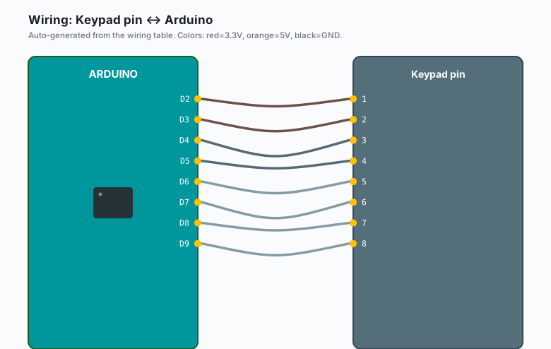
Keypad pins are numbered 1 to 8, left to right, with the keypad face down and the cable pointing toward you. On the standard part, pins 1-4 are the rows and pins 5-8 are the columns.
| Keypad pin | Role | Arduino |
|---|---|---|
| 1 | Row 1 | D2 |
| 2 | Row 2 | D3 |
| 3 | Row 3 | D4 |
| 4 | Row 4 | D5 |
| 5 | Column 1 | D6 |
| 6 | Column 2 | D7 |
| 7 | Column 3 | D8 |
| 8 | Column 4 | D9 |
| Buzzer | Arduino |
|---|---|
| + | D11 |
| - | GND |
How the scan works, in one paragraph: the library drives one row LOW at a time and watches the columns. If you press key “5” (row 2, column 2), the LOW on row 2 leaks out through the key’s contact to column 2, the column pin reads LOW, and the library has a row and a column, which is a key. Any single moment has one row driven, so two simultaneous presses in different rows stay distinguishable (e.g. “1” and “5” together are fine; “1” and “2” together are ambiguous, and the library reports only the first).
Pull-ups: the scan uses INPUT_PULLUP on all 8 pins, so no external resistors. Do not use INPUT mode; floating column pins will phantom-press keys.
Install
The library is in the Library Manager:
Tools >> Manage Libraries >> search “Keypad” by Mark Stanley and Alexander Brevig >> Install.
That is the whole install. There is also a Keypad_I2C variant for a PCF8574 port expander if you ever want the keypad on two wires, but that is an upgrade, not a requirement.
The code
Scan first, trust later. Upload this and open Tools >> Serial Monitor at 9600. Press keys and confirm the right number appears. If pressing “4” shows “6”, your columns are swapped; if the whole row is wrong, your ribbon is offset by one.
// Step 1: identity check. Run this before anything else.
#include <Keypad.h>

const byte ROWS = 4;
const byte COLS = 4;

char keys[ROWS][COLS] = {
  {'1','2','3','A'},
  {'4','5','6','B'},
  {'7','8','9','C'},
  {'*','0','#','D'}
};

byte rowPins[ROWS] = {2, 3, 4, 5};
byte colPins[COLS] = {6, 7, 8, 9};

Keypad keypad = Keypad(makeKeymap(keys), rowPins, colPins, ROWS, COLS);

void setup() {
  Serial.begin(9600);
}

void loop() {
  char key = keypad.getKey();
  if (key) {
    Serial.println(key);
  }
}
Then the real project, a four-digit code lock with beeps and a relay output:
// Code lock: enter 4 digits, correct code pulses the relay.
#include <Keypad.h>

const byte ROWS = 4;
const byte COLS = 4;

char keys[ROWS][COLS] = {
  {'1','2','3','A'},
  {'4','5','6','B'},
  {'7','8','9','C'},
  {'*','0','#','D'}
};

byte rowPins[ROWS] = {2, 3, 4, 5};   // keypad pins 1-4
byte colPins[COLS] = {6, 7, 8, 9};   // keypad pins 5-8

Keypad keypad = Keypad(makeKeymap(keys), rowPins, colPins, ROWS, COLS);

const char CODE[5] = "2580";  // the classic
const int BUZZER = 11;
const int RELAY  = 12;

char entry[5];
byte pos = 0;

void beep(int ms) {
  tone(BUZZER, 2000, ms);
}

void grant() {
  digitalWrite(RELAY, HIGH);
  beep(400);
  delay(700);
  digitalWrite(RELAY, LOW);
}

void deny() {
  beep(80); delay(120);   // two short angry buzzes
  beep(80); delay(120);
}

void setup() {
  pinMode(BUZZER, OUTPUT);
  pinMode(RELAY, OUTPUT);
  Serial.begin(9600);
}

void loop() {
  char key = keypad.getKey();
  if (!key) return;

  if (key == '*') {          // '*' clears and restarts the entry
    pos = 0;
    Serial.println("cleared");
    return;
  }

  entry[pos++] = key;
  beep(40);
  Serial.print(key);

  if (pos == 4) {
    entry[4] = '\0';
    if (strcmp(entry, CODE) == 0) {
      Serial.println("  -> open");
      grant();
    } else {
      Serial.println("  -> denied");
      deny();
    }
    pos = 0;
  }
}
Type 2580 and the relay clicks. Anything else gets the double buzz. Star wipes the entry and starts over, which is what a real keypad door does (the pattern: ’*’ clears, ’#’ could confirm, and A-D are spare function keys).
What you learned
- Matrix scanning: N rows plus M columns reads N x M keys with N+M pins. 8 pins, 16 keys, and the same arithmetic scales up (a 4x4 keyboard of LEDs, a 5x5 grid, a 1x4 “keypad” that is really four buttons).
- INPUT_PULLUP is the whole reason the scan needs no resistors.
- Input sequences (entry buffers, clear key, compare) are the shape of most human-input code, from keypads to menus.
When something breaks
- Pressing keys shows the wrong characters. Ribbon pinout is offset or reversed. Run the scan sketch, press “1”, and see what comes out; remap rowPins and colPins until “1” is “1”. Do not debug the library for this; it is always the wiring.
- Multiple keys read at once, or phantom presses with nothing touched. Two causes: column pins left as plain INPUT (floating; the library handles pull-ups, check your Keypad version), or a ribbon conductor shorting against its neighbor where the cable was bent. Insulate the back with tape.
- Ghost keys with three simultaneous presses. This is the real limitation of matrix scanning (three closed contacts can form a sneak path through a fourth key). For a code lock it does not matter; for a game controller it does. The fix is a diode per key, and that is the point where you just buy the diodes.
- Some keys work, some do not. Probe the ribbon with a multimeter in continuity mode, shorting row 2 to column 2 by hand and pressing “5”. If the meter beeps but the Arduino does not, the mapping is wrong; if the meter does not beep, the membrane trace is broken (pressing too hard in one spot for months does this; the keypad is a consumable).
What to build next
- The memory game on this site: the keypad gives you a real input device for a Simon-style sequence game, four colors on LEDs, four letters on keys.
- A relay-controlled door strike (the relay tutorial covers the safe wiring; the code lock above is the front end).
- The LCD I2C tutorial next to this one: keypad below, display above, and you have a proper user interface instead of Serial Monitor guesswork.