Arduino: animations on an 8x8 LED matrix (MAX7219)
Drive an 8x8 LED matrix with a MAX7219 and Arduino. Build frame-based animations: a smiley, a wave, and a scrolling pixel text. One chip, three wires.
The 8x8 LED matrix with a MAX7219 is the most satisfying cheap display in the Arduino drawer (about $4, and it looks like a real product when it is running). Sixty-four red LEDs, one chip doing all the multiplexing work, and a three-wire interface that does not fight you. This tutorial wires it, drives it, and builds up to real frame-based animation: a bouncing dot, a smiley that blinks, and scrolling text.
The trap I hit: I powered my first matrix from a 3.3V pin “because LEDs are low voltage.” The MAX7219 wants 5V (the datasheet’s minimum supply is 4.0V, and below that the display dims randomly or shows ghost segments). Also, the matrix modules sold today come in two pin orders, VCC-GND-DIN-CS-CLK and the mirror image. If my wiring list below does nothing at all, flip the module around before you rewire anything.
What you need
Needed
- Arduino Uno (or Nano): the board driving everything
- MAX7219 8x8 LED matrix module (the common FC-16 red module, about $4): the display itself; get one on a PCB module, not a bare matrix, the module has the resistors and capacitors already placed
- 5x jumper wires (female-to-male if your module has a pin header): the signal and power connections
- Breadboard (only if your module has bare pins): holds everything while you test
Nice to have
- A second matrix module: daisy-chaining is where this gets fun
- Multimeter: to verify 5V actually arrives at the module (the #1 “matrix shows garbage” cause)
- Soldering iron + solder: only if you bought a module with an unsoldered header
- Helping hands: holds the header straight while you solder it
- Wire stripper: for cutting custom-length jumpers
Wiring
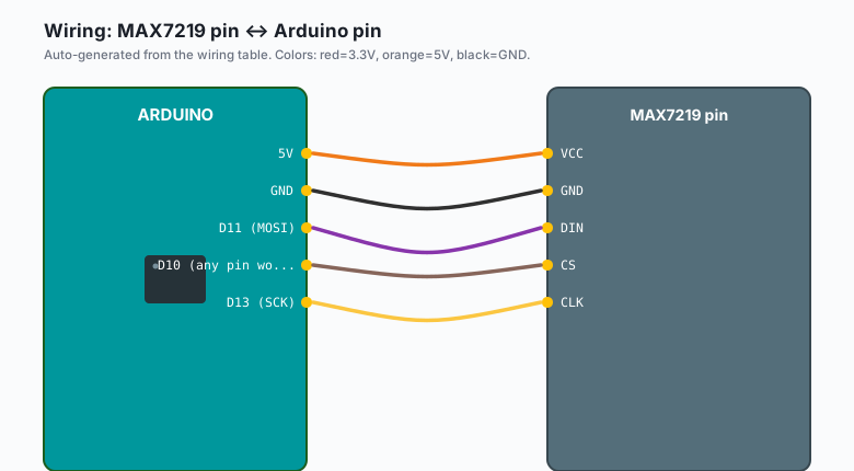
SPI is the interface, and you only use three Arduino pins plus power:
| MAX7219 pin | Arduino pin |
|---|---|
VCC | 5V |
GND | GND |
DIN | D11 (MOSI) |
CS | D10 (any pin works, library default) |
CLK | D13 (SCK) |
Power notes: the MAX7219 wants 5V (it will misbehave on 3.3V), and a full-on matrix can pull 60 to 160 mA, which is fine on USB power but not fine on a 3.3V breakout regulator. Also keep wires short (e.g. under 20 cm); long DuPont runs on CLK are how you get random ghost pixels.
Install
Arduino IDE >> Sketch >> Include Library >> Manage Libraries, search “LedControl”, install the one by E-ALE (LedControl by Eberhard Fahle, maintained by Shay Perera). It is the small, dependency-free library that matches this chip’s simplicity.
(If you later want sprite scrolling and font tables out of the box, the MD_Parola + MD_MAX72xx pair is the heavy option. This tutorial uses LedControl because you can read all of it in one sitting.)
The code
The mental model first: an 8x8 matrix is 8 bytes. Each byte is one row, each bit is one pixel. Animation is nothing more than: draw a frame, wait, draw the next frame. Here is a complete sketch with all three animations built in.
#include <LedControl.h>

// DIN, CLK, CS, number of matrices in the chain
LedControl lc = LedControl(11, 13, 10, 1);

// Each frame is 8 bytes, one per row, top to bottom.
// Bit 7 (leftmost) is the leftmost pixel in the row.
const byte SMILE[8] = {
  0b00111100,
  0b01000010,
  0b10100101,
  0b10000001,
  0b10100101,
  0b10011001,
  0b01000010,
  0b00111100
};

const byte WINK[8] = {
  0b00111100,
  0b01000010,
  0b10100101,
  0b10000001,
  0b10111101,   // one eye closed
  0b10011001,
  0b01000010,
  0b00111100
};

const byte HEART[8] = {
  0b00000000,
  0b01100110,
  0b11111111,
  0b11111111,
  0b01111110,
  0b00111100,
  0b00011000,
  0b00000000
};

void drawFrame(const byte frame[8]) {
  for (int row = 0; row < 8; row++) {
    lc.setRow(0, row, frame[row]);
  }
}

void setup() {
  lc.shutdown(0, false);   // wake the MAX7219 (it starts in shutdown)
  lc.setIntensity(0, 4);   // brightness 0..15, 4 is easy on the eyes
  lc.clearDisplay(0);
}

void loop() {
  // 1. Blinking smiley: hold smile 800 ms, wink 200 ms, repeat
  drawFrame(SMILE);
  delay(800);
  drawFrame(WINK);
  delay(200);

  // 2. Beating heart: big heart, pause, small heart, pause
  // (the small "small heart" is the same heart shifted and shrunk:
  //  here a simple two-frame pulse using intensity instead)
  drawFrame(HEART);
  lc.setIntensity(0, 8);
  delay(300);
  lc.setIntensity(0, 2);
  delay(300);
  lc.setIntensity(0, 8);
  delay(300);
  lc.setIntensity(0, 2);
  delay(300);
  lc.setIntensity(0, 4);

  // 3. Bouncing ball: one dot bouncing diagonally
  signed char x = 0, y = 0;
  signed char dx = 1, dy = 1;
  for (int step = 0; step < 60; step++) {
    lc.clearDisplay(0);
    lc.setLed(0, y, x, true);      // setLed(addr, row, column, on)
    delay(90);
    x += dx;  y += dy;
    if (x == 7 || x == 0) dx = -dx;
    if (y == 7 || y == 0) dy = -dy;
  }
}
Three things worth noticing:
lc.shutdown(0, false)is not optional. The MAX7219 boots in shutdown mode, which is why the untouched matrix looks dead. This one line is the “why is my matrix blank” answer most of the time.setIntensity(0, 4): brightness is a duty-cycle thing, 0 to 15. Full 15 with all 64 LEDs on draws real current (e.g. 160 mA worst case, so keep it at 4 or 5 for breadboard testing).- The animation loop is the whole idea: draw frame, delay, draw frame. The bouncing ball is two lines of physics (position plus delta, bounce at the walls) riding on top of that.
A second pattern: scrolling text without a library
The classic “scrolling pixel text” is a frame buffer you shift left one column per tick. The 5x7 font for “A” as raw columns:
const byte A_COLUMNS[5] = {
  0b01111100,   // col 0
  0b00010010,   // col 1
  0b00010001,   // col 2
  0b00010010,   // col 3
  0b01111100    // col 4
};

void scrollLetter() {
  // Draw letter at column offset 8, then shift left 16 times
  // (8 to enter, 8 to leave).
  for (int offset = 8; offset > -6; offset--) {
    lc.clearDisplay(0);
    for (int col = 0; col < 5; col++) {
      int screenCol = offset + col;
      if (screenCol < 0 || screenCol > 7) continue;
      lc.setColumn(0, screenCol, A_COLUMNS[col]);
    }
    delay(120);
  }
}
setColumn() is the rotate-your-head call: columns run the other way
from rows on this chip, and the LedControl API makes you flip your
mental picture (this trips everyone exactly once).
What you learned
- The MAX7219 turns 16 Arduino pins of LED-driving into 3 pins of SPI, and it handles the multiplexing so no LED or Arduino pin is overstressed.
- A frame is 8 bytes; animation is frames in sequence. Any drawing you can express as 64 bits, you can animate.
shutdown(false)at setup and a sane intensity are the two setup lines that keep the matrix from looking broken when it is not.
When something breaks
- Completely dark matrix: the shutdown bit (call
lc.shutdown(0, false)), a swapped DIN/CLK pair, or a module wired to 3.3V. Check power first, then swap the two signal wires, then the shutdown call. - Garbage pixels, random rows lit: loose breadboard contact on CLK, or wires longer than about 20 cm picking up noise. Shorten the wires and reseat everything (this is also the symptom of a matrix powered through a weak regulator).
- Rows/columns mirrored or rotated: your module is a different
variant than the FC-16 wiring the library assumes. Nothing is broken;
the setRow/setColumn bit order just does not match. Test with a
single
setLed(0, 0, 0, true)and adjust which corner that is. - Matrix dims after a few seconds: the Arduino’s 5V rail is sagging (USB port or cable too weak), or intensity is at 15 with all LEDs on. Try a powered hub or a supply that actually delivers 500 mA.
- Cascaded second matrix shows the first matrix’s data: the
MAX7219 chain is a shift register; the first 8 bytes shifted land on
the last module in the chain. Address them with
LedControl(DIN, CLK, CS, 2)and use device index 0 and 1 (the order is opposite to the physical chain, which surprises everyone).
What to build next
- Chain a second MAX7219 module and scroll text across 16 columns wide (same three wires, the library takes a device count).
- The traffic light tutorial pairs this matrix with a millis() state machine: matrix as the pedestrian countdown display.
- The EEPROM tutorial stores your custom frames so a different animation survives a power cycle (e.g. a “message of the day” the device remembers).
- The night security light tutorial and this matrix share the same lesson: light output is easy, but deciding when it runs is the actual project.