Arduino: build a light-following robot with LDRs
A 2WD robot that chases a flashlight beam using two LDR eyes and bang-bang steering. Phototaxis for twelve dollars of parts.
The line-follower robot on this site chases a tape line. This one chases a flashlight. Same chassis, same motor driver, same control loop: read two sensors, subtract, steer toward whichever eye sees more. Biologists call it phototaxis (e.g. a moth doing the exact same thing to your porch light). We call it the second robot you should build, because it teaches differential steering with sensors you already understand.
The build: two light-dependent resistors mounted on the front of a 2WD chassis, one behind a cardboard baffle on the left, one on the right. The Arduino reads both with analogRead, computes the difference, and drives the motors at different speeds so the nose turns toward the brighter side. No library, no PID, one serial plot.
The part I want to name first: the baffle is not optional. I built my first light-follower without one, watched both LDRs read within 20 counts of each other no matter where I pointed the flashlight, and spent an hour suspecting the code. The code was fine. Both eyes could see the same light, so the difference was always near zero. A folded index card between the sensors fixed it in thirty seconds. Hardware beats software when the hardware is the problem.
What you need
Needed
- Arduino Uno (or Nano, same code, same pins)
- 2WD robot chassis kit with two geared DC motors and wheels (the yellow-TT-motor kit, about $15; the same kit as the line-follower robot, so build one and reuse it for the other)
- L298N motor driver module (about $2)
- 2x LDR modules (the 3-pin LM393 comparator boards will not work here, they give you a yes/no output; you want the bare LDR or a module with an analog pin, about $1)
- 2x 10k ohm resistors (for the voltage divider, if your LDRs are bare)
- 7.4V battery pack (2x 18650) for the motors
- Jumper wires and double-sided tape or hot glue for mounting
Why bare LDRs or analog-output modules: this whole robot lives on the difference between two light levels. A comparator module destroys that information before the Arduino ever sees it.
Nice to have
- Wire stripper (you will trim the LDR legs)
- Multimeter (for confirming the divider actually divides)
- Helping hands or a small vise (holding the baffle while the glue sets)
- Anti-static wristband (the LDRs survive abuse, the Uno is tougher than people think, but the wristband costs less than a new Uno)
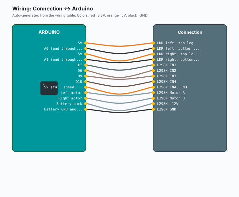
Wiring
| Connection | Arduino |
|---|---|
| LDR left, top leg | 5V |
| LDR left, bottom leg | A0 (and through 10k to GND) |
| LDR right, top leg | 5V |
| LDR right, bottom leg | A1 (and through 10k to GND) |
| L298N IN1 | D5 |
| L298N IN2 | D6 |
| L298N IN3 | D9 |
| L298N IN4 | D10 |
| L298N ENA, ENB | 5V (full speed, bang-bang only) |
| L298N Motor A | Left motor |
| L298N Motor B | Right motor |
| L298N +12V | Battery pack |
L298N GND | Battery GND and Arduino GND (common ground, always) |
Each LDR forms a voltage divider with its 10k resistor: 5V, LDR, then the junction goes to the analog pin, then the 10k goes to GND. More light means lower LDR resistance, which pulls the pin toward 5V. More light reads as a higher number. Say that out loud once, because getting it backwards is the classic bug.
Mount the LDRs on the front edge of the chassis, angled outward about 30 degrees, with the baffle (a folded index card or foam strip, 4 cm tall) standing between them. Both faces point slightly away from each other. The baffle shadows the far eye when light comes from one side.
If your LDR leads are short, the LDR on a moving robot vibrates loose. Solder a short pigtail or hot-glue the lead at the pin. A robot that steers by reading a wire that is half-fallen-out steers by reading noise.
Install
Nothing to install. analogRead and digitalWrite are in the core.
Open the IDE, pick your board under Tools >> Board, pick the port under Tools >> Port, and you are ready. If the port list is empty, the usual fix is a genuine data-capable USB cable (e.g. the charge-only cable that shipped with a phone).
The code
// Light-follower: two LDR eyes, differential drive, bang-bang steering.
// More light = lower LDR resistance = higher analog reading (divider: LDR on top, 10k to GND).

const int LDR_LEFT  = A0;
const int LDR_RIGHT = A1;

// L298N pins, same as the line-follower robot
const int IN1 = 5;
const int IN2 = 6;
const int IN3 = 9;
const int IN4 = 10;

// Deadband: how big the left/right difference must be before we steer.
// Too small and the robot jitters; too big and it ignores gentle light.
const int DEADBAND = 60;

void setup() {
  pinMode(IN1, OUTPUT);
  pinMode(IN2, OUTPUT);
  pinMode(IN3, OUTPUT);
  pinMode(IN4, OUTPUT);
  Serial.begin(9600);
}

void drive(int leftDir, int rightDir) {
  // leftDir / rightDir: 1 = forward, 0 = stop
  digitalWrite(IN1, leftDir  ? HIGH : LOW);
  digitalWrite(IN2, leftDir  ? LOW  : HIGH);
  digitalWrite(IN3, rightDir ? LOW  : HIGH);
  digitalWrite(IN4, rightDir ? HIGH : LOW);
}

void loop() {
  int left  = analogRead(LDR_LEFT);
  int right = analogRead(LDR_RIGHT);
  int diff  = left - right;

  Serial.print(left);
  Serial.print('\t');
  Serial.print(right);
  Serial.print('\t');
  Serial.println(diff);

  if (diff > DEADBAND) {
    drive(1, 0);   // light is on the left: stop right wheel, swing left
  } else if (diff < -DEADBAND) {
    drive(0, 1);   // light is on the right: stop left wheel, swing right
  } else {
    drive(1, 1);   // roughly centered: full speed ahead
  }

  delay(50);
}
This is the same bang-bang control the line-follower uses, pointed at light instead of tape. The Serial prints are there on purpose: open Serial Monitor (Tools >> Serial Monitor, 9600 baud), aim the flashlight left and right, and confirm left goes high when light is left before you ever set it on the floor. Watching the numbers move before the robot moves is the cheapest debugging you will ever do.
What you learned
- Differential steering from a sensor difference: subtract, apply a deadband, drive the wheels unevenly. One pattern, zero libraries.
- A voltage divider turns resistance (the LDR’s language) into voltage (the ADC’s language).
- A physical baffle is part of the sensor system. When two sensors must disagree to be useful, shape what they can see.
When something breaks
- Both LDRs read nearly the same no matter where the light is. The baffle is missing or too short. Raise it or widen the angle of the two sensors. Second cause: the LDRs are wired upside down (10k to 5V instead of to GND), which inverts the readings on both at once and shrinks the apparent difference.
- The robot runs away from the flashlight. Either the motors are swapped left-for-right, or your divider orientation is inverted. Swap the two motor connectors first (ten seconds), re-check the readings second.
- It ignores the flashlight in daylight. Room light saturates both eyes, and the torch adds too little on top. Dim the room or use a focused torch. Also worth checking: your readings at full light should reach into the 900s, not hover near 700.
- It jitters near the threshold, twitching left and right. The difference is straddling the deadband. Raise DEADBAND to 100 and test again.
What to build next
- The line-follower robot on this site: same chassis, same driver, same control loop, different sensor. Build both and you will never mix up “sensor difference” thinking again.
- The night security light: one LDR, threshold logic, real lamp control. It is the stationary cousin of this build.
- Add PWM speed control: move the L298N enables to PWM pins and steer proportionally instead of bang-bang. That is the honest first step toward the PID motor control in the line-follower’s next steps.