Arduino: build a line-following robot
A 2WD robot that follows a black electrical-tape line using three IR reflectance sensors. Bang-bang control done honestly, PID optional.
The line-follower is the robot everyone should build first. It has one job (steer so the line stays under the middle sensor), the parts cost about $25, and it teaches the control-loop idea that scales all the way up to real robotics: read sensors, decide, correct, repeat.
This version uses three IR reflectance sensors and bang-bang control. It works well enough to be satisfying, and it leaves the PID upgrade as the natural next step.
What you need
- Arduino Uno (or Nano, same code)
- 2WD robot chassis kit (two geared DC motors, wheels, battery holder, about $15; the yellow-TT-motor kit is the standard)
- L298N motor driver module (about $2)
- 3x TCRT5000 IR reflectance sensor modules (or one 3-channel board that packages the same sensor, about $3)
- Black electrical tape (the track)
- A white surface (poster board, or a floor tile)
Why IR reflectance over a camera: at this price point the IR sensor answers one question (line under me: yes/no) with zero processing. A camera solution is a different project with a different budget.
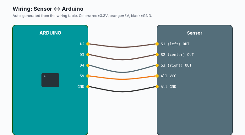
Wiring
| Sensor | Arduino |
|---|---|
| S1 (left) OUT | D2 |
| S2 (center) OUT | D3 |
| S3 (right) OUT | D4 |
All VCC | 5V |
All GND | GND |
| L298N | Arduino |
|---|---|
| IN1 | D5 |
| IN2 | D6 |
| IN3 | D9 |
| IN4 | D10 |
| ENA, ENB | 5V (full speed) or PWM pins for speed control |
| Motor A | Left motor |
| Motor B | Right motor |
| +12V | Battery pack (2x 18650, 7.4V) |
GND | Battery GND + Arduino GND (common ground, always) |
The three sensors mount on the front edge of the chassis, 15 mm apart, 10 mm above the floor. Spacing matters more than sensor quality: too close and the robot twitches, too far and it overshoots corners.
The code
const int LEFT = 2, CENTER = 3, RIGHT = 4;
const int IN1 = 6, IN2 = 9, IN3 = 10, IN4 = 11;

void setup() {
  pinMode(LEFT, INPUT); pinMode(CENTER, INPUT); pinMode(RIGHT, INPUT);
  pinMode(IN1, OUTPUT); pinMode(IN2, OUTPUT);
  pinMode(IN3, OUTPUT); pinMode(IN4, OUTPUT);
}

void drive(int l, int r) {   // l,r: +1 forward, -1 back, 0 stop
  digitalWrite(IN1, l > 0); digitalWrite(IN2, l < 0);
  digitalWrite(IN3, r > 0); digitalWrite(IN4, r < 0);
}

void loop() {
  // TCRT modules: LOW = black line absorbed, HIGH = white floor reflected
  int l = digitalRead(LEFT);
  int c = digitalRead(CENTER);
  int r = digitalRead(RIGHT);

  if (c == LOW && l == HIGH && r == HIGH)      drive(1, 1);   // straight
  else if (l == LOW)                            drive(0, 1);   // line left, turn left
  else if (r == LOW)                            drive(1, 0);   // line right, turn right
  else if (l == LOW && c == LOW && r == LOW)    drive(0, 0);   // all black: stop/end
  else                                          drive(1, 1);   // lost briefly: coast
}
Differential steering is the trick: to turn left, stop or reverse the left wheel and drive the right one. Two wheels, two decisions, no steering servo.
Calibrating the sensors
The TCRT5000 modules have a pot each. On your track surface:
- Place the sensor over plain white floor.
- Adjust its pot until the onboard LED just turns on (reflected = detected).
- Place it over the black tape; the LED must turn off.
Three sensors, three pots, five minutes. Skimp on this and the robot will follow the edge of the track or ignore it entirely (e.g. the classic “my robot runs away from the line” is one sensor inverted by its pot).
The PID upgrade (the next 40 minutes)
Bang-bang control wobbles on smooth corners because the correction is
always full-scale. The fix is proportional control: steer in proportion
to how far off the line you are. With the center sensor over the line,
error = 0; left sensor sees line, error = -1; right sees it, error = +1.
Weighted average of the three gives you a continuous error signal, and
turn = Kp * error smooths the whole thing out. Kp of about 40 (on a
0-255 PWM scale) is a starting point, then tune on your track.
What you learned
- Differential drive: two wheels, no steering mechanism.
- Bang-bang control works and teaches the loop; proportional control is the upgrade path.
- Sensor calibration against your actual track surface is not optional.
When something breaks
- Robot runs away from the line: one sensor reads inverted (pot mis-adjusted) or left/right are swapped in code. Swap D2 and D4 wires and see if behavior inverts; that tells you which it is.
- Motors hum but do not turn: the L298N needs at least 7V on its motor supply; 4x AA (6V) is under its dropout. Two 18650s fix it.
- Jerky, oscillating hard: sensors too far apart, or gain too high when you have added proportional steering. Move sensors closer to 10-12 mm spacing.
- Works on the bench, fails on carpet: TCRT5000 needs about 5 mm floor clearance and carpet scatters IR. Hard floor for testing, or add shims to raise the sensor board.
What to build next
- The obstacle-avoidance robot swaps the line sensors for an ultrasonic eye; same chassis, same L298N.
- The traffic light project is the state-machine refresher this robot’s decision table uses.
- The ESP32 robot base project is the Wi-Fi upgrade of this same chassis.