Arduino: hardware interrupts, the right way to react to events
Wire a button to an interrupt pin and react to it instantly. The pattern that makes pin-change detection feel like magic, and the rules you cannot break.
I wired a button to pin 7 on an Arduino once and wrote a sketch that
checked it in loop(). The button worked, mostly. Then I added a few
delay(1000) calls for a status blink and the button started dropping
presses. By the time I was blinking an LED, reading a sensor, and
talking over serial, the button was missing roughly half the presses.
The fix is interrupts. The Arduino has dedicated hardware that watches a pin for you while your code does other things. When the pin changes, your code gets interrupted (which is the literal meaning), runs a small function you wrote, and picks up where it left off. No polling delay, no missed button press.
This is the tutorial I wish I had read before trying to debounce my way out of the problem.
What you need
- Any Arduino board (Uno, Nano, Mega). The MKR and ESP32 also work, but with a slightly different API.
- A momentary pushbutton
- A 10k ohm resistor (pull-down)
- Jumper wires
- USB cable
The Uno has interrupt-capable pins on digital 2 and 3 only. If you want more, use the Mega (six interrupt pins) or the ESP32 (every pin is interrupt-capable).
Wiring
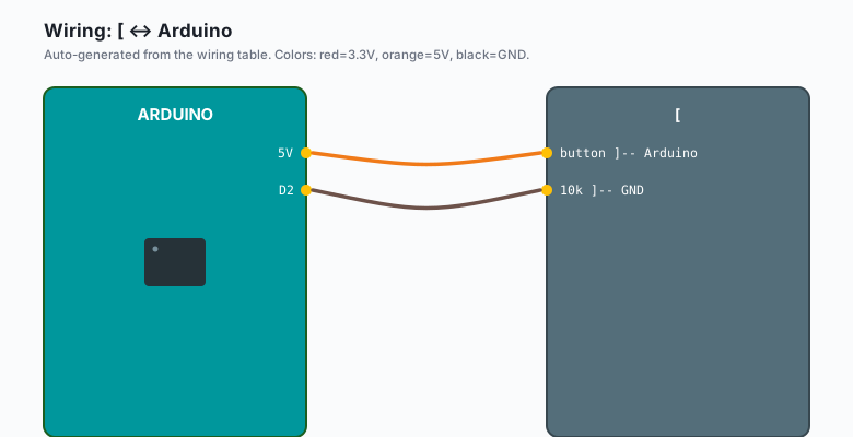
Arduino 5V --[ button ]-- Arduino D2
                          |
                       (button also has a leg on D2)

Arduino D2 --[ 10k ]-- GND
The resistor pulls D2 to ground when the button is open, so the pin reads LOW. When you press the button, D2 connects to 5V and reads HIGH. That is a pull-down resistor. The alternative is to wire the button to GND and use the Arduino’s internal pull-up (more on that in a minute).
   5V o----[ button ]----o----o D2
                          |
                       [ 10k ]
                          |
                         GND
The code
const byte LED_PIN = 13;
const byte BUTTON_PIN = 2;
volatile bool buttonPressed = false;

void setup() {
  pinMode(LED_PIN, OUTPUT);
  pinMode(BUTTON_PIN, INPUT);
  attachInterrupt(digitalPinToInterrupt(BUTTON_PIN), onPress, RISING);
}

void loop() {
  if (buttonPressed) {
    buttonPressed = false;
    digitalWrite(LED_PIN, HIGH);
    delay(50);
    digitalWrite(LED_PIN, LOW);
  }
  // do other stuff here; the button still gets attention
}

void onPress() {
  buttonPressed = true;
}
The whole thing comes down to one line: attachInterrupt(...).
The first argument is the interrupt number, but you almost never want
the bare number. digitalPinToInterrupt(pin) converts a pin number
to the right interrupt number for whichever board you are on. The
second argument is the function to call when the event happens. The
third is the trigger: RISING (LOW to HIGH), FALLING (HIGH to LOW),
or CHANGE (either direction).
What you learned
The volatile keyword is the most important line in this sketch and
it is the one that trips up beginners. volatile tells the compiler
“this variable can change outside the normal flow of your code, so do
not optimize reads of it into a register.” Without volatile, the
loop might cache the value and never see the change. With it, every
read goes to RAM.
The second thing: the function you pass to attachInterrupt is called
an ISR (Interrupt Service Routine). ISRs have rules.
- No
Serial.print. The serial hardware shares an interrupt with some ISRs, and you can deadlock. The fix is to set a flag in the ISR and print inloop(). - No
delay().delay()itself uses interrupts to count milliseconds. Calling it from an ISR that preempts the timer interrupt will hang the chip. - No
malloc. The heap is not safe inside an ISR. Same reason. - Keep it short. The shorter the ISR, the less time your main code spends paused. Milliseconds are too long. Microseconds are the budget.
A common pattern: the ISR sets a flag, the main loop checks the flag and does the work. That is what this sketch does.
When something breaks
- The button triggers twice on one press. This is bounce. Real buttons have metal contacts that bounce for a few milliseconds before settling. Fix it with a 50-millisecond ignore window in your loop, or by tracking the last time you saw a press.
- Nothing happens at all. You probably have the wrong pin. The
Uno can only interrupt on digital 2 and 3. If you wired to pin 7
by accident, the
attachInterruptcall still compiles but does nothing. - The LED stays on after the press. You forgot to clear the flag
inside the
if. The ISR set it, the loop saw it, the loop turned the LED on, but the flag is still set so next time through the loop the LED turns on again. Clear it. - The compiler complains about
digitalPinToInterrupt. Some older cores do not have that macro. Use the raw interrupt number (0 for pin 2, 1 for pin 3 on the Uno) instead.
The “interrupt every microsecond” gotcha
If you wire a button directly without debouncing, the ISR can fire multiple times for one press. Now imagine the button is a 1 kHz square wave from a sensor. The ISR fires 1000 times per second, every second, forever. Your main loop never gets a chance to run.
Two fixes. First, debounce in software (a 50 ms ignore window in the
loop, or a 50 ms ignore window in the ISR with millis()). Second,
if you genuinely have a high-frequency signal, use a hardware timer
interrupt to count pulses, not a pin-change interrupt.
When NOT to use interrupts
For a slow sensor you read once a second, polling in loop() is
simpler and easier to debug. Interrupts add three things you have to
get right (volatile, atomicity, debouncing) for one thing you get
back (no missed events between polls). If you do not need instant
response, do not pay the cost.
The threshold I use: if the event happens more often than my loop()
runs, and the event matters, I use an interrupt. Otherwise I poll.
The 2-pin vs any-pin trade-off
The ATmega328P (Uno, Nano) has exactly two external interrupt pins (2 and 3) and 20 GPIO pins total. The ATmega2560 (Mega) has six. The ESP32 has an interrupt on every pin. The SAMD21 (MKR, Nano Every) also has interrupts on every pin.
If you are on an Uno and need more than two interrupt sources, you
have three options: use Pin Change Interrupts (PCINT, more code),
upgrade to a Mega, or multiplex the inputs and read them with a
shift register.
ISR priority on different boards
The Uno has a fixed interrupt priority. Some interrupts can preempt
others (e.g. the timer interrupt can preempt a pin change). On the
ESP32 you can set priorities with attachInterrupt with a priority
argument. On the Uno you cannot. If two interrupts fire at the same
time on a Uno, the one with the lower vector number wins. There is
no “interrupt priority” knob for you to turn.
What to build next
- A button that toggles the LED on and off (track the state in a variable, flip it in the loop).
- A button that controls motor speed through an H-bridge.
- A rotary encoder, which is two interrupts plus a state machine (covered in the encoder tutorial).
- A wake-up from sleep:
attachInterruptworks while the chip is asleep, and a button press can wake it.
The encoder tutorial is the natural next project. The H-bridge plus encoder is a closed-loop motor, which is the start of a real robot drive train.