Arduino: drive a DC motor with the L298N H-bridge
Wire an L298N module to an Arduino and control a DC motor forward, reverse, and at variable speed with PWM. The H-bridge pattern that runs most hobby robots.
You cannot drive a motor directly from an Arduino pin. The pin sources about 20 mA, a motor wants 200 mA to a few amps, and the back-EMF from a spinning motor will fry the pin in microseconds.
The L298N is the workhorse module that fixes this. It is a dual H-bridge on a small green PCB with screw terminals. You give it power (a battery, usually 7-12V for hobby motors) and three logic pins from the Arduino. It does the high-current switching and protects the Arduino from the motor’s electrical noise.
This is the pattern I use in every robot I build. The same wiring works on a Uno, a Mega, an ESP32, a Pico. The code is the same in Arduino C. The differences are at the edges (PWM frequency, current capacity).
What you need
- L298N motor driver module (the common green one, $2-$3)
- DC motor (a small gearmotor, 6V to 12V, less than 2A)
- Arduino (any board)
- Battery pack (4xAA or a 7.4V LiPo, depending on the motor)
- Jumper wires
- USB cable
The L298N module has screw terminals for the motor power and the motor outputs, and header pins for the logic inputs. It also has a 5V regulator that can power the Arduino’s 5V rail if you wire it correctly. Be careful with that: if you feed the Arduino’s 5V from both USB and the L298N, you can back-power the USB port and confuse your computer.
Wiring
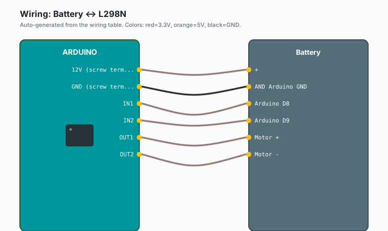
L298N 12V (screw terminal) -- Battery +
L298N GND (screw terminal) -- Battery - AND Arduino GND
L298N 5V (header pin)      -- (do NOT connect to Arduino 5V; remove jumper if powering Arduino from USB)

L298N IN1 -- Arduino D8
L298N IN2 -- Arduino D9
L298N ENA -- Arduino D10   (PWM-capable pin)

L298N OUT1 -- Motor +
L298N OUT2 -- Motor -
The L298N has two H-bridges. You can drive two motors. For one motor you use IN1, IN2, ENA, OUT1, OUT2. The other half of the module is unused.
The 5V header on the L298N is a 5V output from the on-board regulator, intended to power logic. With the jumper on (factory default), the regulator is enabled. If you want the Arduino to power the L298N’s logic instead, remove the jumper. The most common setup is to leave the jumper on and let the L298N power the Arduino’s 5V rail through this pin, but only if the Arduino is not also connected to USB.
The cleanest setup: remove the 5V jumper, run the Arduino from USB, share the GND between battery, Arduino, and L298N.
The code
const int IN1 = 8;
const int IN2 = 9;
const int ENA = 10;   // PWM pin

void setup() {
  pinMode(IN1, OUTPUT);
  pinMode(IN2, OUTPUT);
  pinMode(ENA, OUTPUT);
}

void stop() {
  digitalWrite(IN1, LOW);
  digitalWrite(IN2, LOW);
  analogWrite(ENA, 0);
}

void forward(int speed) {
  digitalWrite(IN1, HIGH);
  digitalWrite(IN2, LOW);
  analogWrite(ENA, speed);   // 0-255
}

void reverse(int speed) {
  digitalWrite(IN1, LOW);
  digitalWrite(IN2, HIGH);
  analogWrite(ENA, speed);
}

void loop() {
  forward(200);
  delay(2000);
  stop();
  delay(500);
  reverse(200);
  delay(2000);
  stop();
  delay(500);
}
Four functions: forward, reverse, stop, and the implicit
coast (set both IN pins LOW but let ENA float). The stop()
function above is “brake” (both pins LOW, ENA enabled at 0 PWM
which short-circuits the motor). Brake stops the motor faster
than coast. Coast lets the motor spin down on its own.
The four states: forward, reverse, brake, coast
The L298N can put the motor in four electrical states, and they behave differently:
- Forward: IN1 HIGH, IN2 LOW, ENA PWM. Motor spins one way.
- Reverse: IN1 LOW, IN2 HIGH, ENA PWM. Motor spins the other.
- Brake: IN1 LOW, IN2 LOW, ENA HIGH (or PWM with any value). Motor stops hard. Energy is dissipated in the L298N.
- Coast: IN1 LOW, IN2 LOW, ENA LOW. Motor is disconnected, spins down gradually. Energy goes back to the supply (a small amount, on the L298N; on a smarter driver, this is called “regenerative braking”).
For a robot, brake is the right stop. For a wheel that needs to freewheel when the robot is not driving, coast is right.
The enable pin for PWM speed control
ENA (and ENB for the second channel) is the PWM speed control.
You can drive ENA with analogWrite() on any PWM-capable pin.
The frequency is the Arduino default, about 490 Hz on most pins
(980 Hz on pins 5 and 6 on the Uno). For DC motors, the
frequency does not matter much. For steppers or other inductive
loads, you might want a higher frequency, which means changing
the timer config (covered in the L298N with a stepper tutorial).
speed in the code above is 0-255, matching the analogWrite()
range. speed = 0 with ENA HIGH is brake. speed = 0 with ENA
LOW is coast. They are not the same.
The 2A per channel limit
The L298N is rated for 2A continuous per channel, 3A peak. The actual thermal limit is closer to 1A continuous without a heatsink. If you push more current than that, the chip goes into thermal shutdown, which looks like the motor randomly stopping and starting.
The fix is either: use a bigger motor driver (BTS7960, DRV8871), or add a real heatsink to the L298N. The little clip-on aluminum heatsink that ships with some modules is barely adequate. A proper one (with thermal paste) is better.
The voltage drop (1.5V per side)
The L298N uses bipolar transistors, not MOSFETs. Each side of the H-bridge drops about 1.5V. If you power the motor with 12V, the motor sees about 9V after the drop. If you power it with 6V, the motor sees 3V.
For a 6V motor, that means you cannot run it at full speed from a 6V supply through an L298N. You need a 7.5V or 9V supply to get the rated speed. This is the most common confusion when people first use the L298N. The motor “feels weak” because the voltage is too low after the drop.
MOSFET-based drivers (BTS7960, DRV8871) drop about 0.2V, which makes them a much better choice for low-voltage motors.
The heatsink requirement
The 1.5V drop times 1A of current is 1.5W of heat dissipated in the chip. That is enough to heat it well past 100 degrees C, which is the thermal limit. The chip will throttle, or shut down, or (worst case) desolder itself from the PCB.
If your motor draws more than about 0.5A continuously, attach the heatsink with thermal paste. If the motor draws more than 1A, use a bigger driver. The DRV8871 is a drop-in replacement for the L298N (different pinout, same logic) and handles 3.6A continuous without breaking a sweat.
Alternatives: BTS7960 and DRV8871
For higher current or lower voltage drop, the two common upgrades:
- BTS7960: 43A, drops about 0.4V. Big module, big heatsink already attached. Use for wheelchair motors, large gearmotors. The pinout is different (uses an enable and a direction pin rather than two inputs).
- DRV8871: 3.6A continuous, drops about 0.2V. Small breakout, no heatsink needed for typical hobby motors. The simplest upgrade path. Different pinout, same logical interface.
For a first robot, the L298N is fine. For a second robot, switch to the DRV8871. The code is the same.
The “regenerative braking” pattern
A regenerative brake turns the motor into a generator and dumps the energy back into the battery. The L298N does not do this natively (it can, but the internal diodes are too small for any real current). The DRV8871 does support it, in a limited way.
The effect on a robot: when you let off the throttle, a regen system slows the robot down (using the motor as a brake) and recovers some energy. For a small robot with a tiny battery, the energy recovered is negligible. For a larger robot, it matters.
You usually do not need regen. Brake (stop() with ENA HIGH) is
fine for most projects.
When something breaks
- Motor does not move at all. Check the wiring, especially the motor power and ground. The L298N needs both 12V (motor power) and 5V (logic) to switch.
- Motor moves at full speed, no PWM control. ENA is not connected, or ENA is on a non-PWM pin. Move it to a PWM pin (3, 5, 6, 9, 10, or 11 on the Uno).
- Arduino resets when the motor starts. The motor is drawing too much current and the supply is browning out. Add a decoupling capacitor (100 uF) on the L298N’s 5V rail, or use a separate supply for the Arduino.
- Motor gets hot but does not spin. The motor is shorted or the load is too high. Check for binding in the gearbox or wheels.
- Motor runs backward when you call
forward(). The motor wires are reversed. Either swap the motor wires on OUT1/OUT2, or swap the IN1/IN2 logic in your code.
What to build next
- A two-wheel robot with two L298N channels (or one L298N with two motors).
- A PID-controlled motor that holds a target speed.
- A stepper motor (the L298N also drives steppers, but the current limiting is different; the A4988 is a better stepper driver).
The two-wheel robot is in the next tutorial. The PID motor control is in the book Arduino Robotics, with a chapter on encoder feedback and closed-loop speed control.