Arduino: read a rotary encoder, position and direction
Wire a rotary encoder to two interrupt pins and track position, direction, and speed. The pattern that lets a motor know where it is.
A potentiometer tells you absolute position. Turn it to 25%, you read 25%. Unplug it, plug it back in, you still read 25%.
A rotary encoder is different. It tells you “the shaft has moved N detents in the clockwise direction” or “M detents in the counter-clockwise direction.” The absolute position is up to you to track. Unplug it, plug it back in, you start over from zero (unless you save the count to EEPROM).
The benefit is no end stops. A pot only turns 270 degrees. An encoder spins forever, and you count the clicks.
This is the sensor behind closed-loop motor control. The motor turns, the encoder counts the turns, the code knows how far the motor has gone and how fast. The H-bridge tutorial showed you how to spin the motor. This one shows you how to know what the motor is doing.
What you need
- Rotary encoder (the KY-040 is the most common hobby one; the NEMA-17 with encoder is the typical stepper-style one)
- Arduino (Uno, Nano, Mega)
- Jumper wires
- USB cable
For a motor with an encoder, you also need a motor driver (L298N, BTS7960, or DRV8871, covered in the previous tutorial). For just an encoder on a knob, you only need the encoder.
How a rotary encoder works
A rotary encoder has two output pins, usually called A and B (or CLK and DT). As the shaft turns, the two pins produce square waves that are 90 degrees out of phase with each other. The pattern is called “quadrature.”
When the shaft turns clockwise, A leads B. When it turns counter-clockwise, B leads A. The 90-degree phase difference is what tells you the direction.
A “click” on a typical encoder is one full quadrature cycle. The encoder I am holding has 20 detents per revolution, which is 20 full cycles, which is 20 ticks if you read A and B as a pair. If you count every edge of A and every edge of B (rising and falling), you get 4 ticks per detent, or 80 per revolution. That is the 600 PPR vs 2400 PPR distinction: PPR is “pulses per revolution,” and 4x decoding is the standard.
Wiring
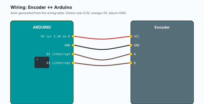
Encoder VCC -- Arduino 5V (or 3.3V on ESP32, check the encoder)
Encoder GND -- Arduino GND
Encoder A   -- Arduino D2   (interrupt pin)
Encoder B   -- Arduino D3   (interrupt pin)
Some encoders (the KY-040) also have a pushbutton switch on the shaft. Wire that to another digital pin if you want it. The button is a separate component, not part of the encoder logic.
The encoder needs 5V on a 5V Arduino. On a 3.3V board, check the encoder’s spec; most are fine with 3.3V, but the output is open-drain on the cheap ones, which means you need pull-up resistors. The KY-040 has built-in pull-ups, so the wiring is the same on either board.
The code
const int ENC_A = 2;
const int ENC_B = 3;

volatile long position = 0;

void setup() {
  Serial.begin(9600);
  pinMode(ENC_A, INPUT_PULLUP);
  pinMode(ENC_B, INPUT_PULLUP);
  attachInterrupt(digitalPinToInterrupt(ENC_A), onChange, CHANGE);
  attachInterrupt(digitalPinToInterrupt(ENC_B), onChange, CHANGE);
}

void loop() {
  static long lastPrint = 0;
  long p = position;
  if (millis() - lastPrint > 100) {
    Serial.println(p);
    lastPrint = millis();
  }
}

void onChange() {
  bool a = digitalRead(ENC_A);
  bool b = digitalRead(ENC_B);
  // The state table:
  // A B  |  Action
  // 0 0  |  no change
  // 0 1  |  +1
  // 1 0  |  -1
  // 1 1  |  no change
  if (a == b) {
    position++;
  } else {
    position--;
  }
}
Both pins trigger the same ISR on every change. The ISR reads both pins and updates the position based on the current state.
The trick is the a == b line. When the two signals are 90
degrees out of phase, half the time they are equal (in the “both
HIGH” or “both LOW” stable states) and half the time they are
unequal (during transitions). Counting the equality transitions
gives you 2x the basic rate; counting all transitions gives you
4x.
This code counts the equality transitions (2x decoding). To do 4x, change the ISR to track the previous state and look up the direction from a state table.
The “interrupt on change” pattern
The reason for the interrupts: the encoder can turn at any speed.
If you turn the knob quickly, the edges come faster than your
loop() runs. If you poll, you miss edges. The interrupt catches
every edge, no matter how fast the shaft turns.
A 600 PPR encoder at 100 RPM is 1000 edges per second. The Arduino
Uno can handle interrupts at that rate easily. At 10,000 RPM, you
are at 100,000 edges per second, which is also doable but you
will spend most of your CPU time in the ISR. For a knob on a UI,
this does not matter. For a motor at high speed, the ISR needs to
be tiny (which is why we update a volatile long and not a
Serial.print inside the ISR).
The position math: one click = X counts
The relationship between “detents” and “counts” depends on the encoder and your decoding:
- A typical encoder has 20 detents per revolution.
- 1x decoding: 1 count per detent = 20 per revolution.
- 2x decoding (the code above): 2 counts per detent = 40 per revolution.
- 4x decoding: 4 counts per detent = 80 per revolution.
The encoder’s datasheet calls this “PPR” (pulses per revolution) or “CPR” (counts per revolution, which is 4x PPR). A 600 PPR encoder with 4x decoding is 2400 CPR.
For a motor, the position math is the same: count the edges, multiply by degrees per count, you get the shaft angle.
Debouncing the encoder in software
Mechanical encoders bounce. The signal can chatter for a few microseconds before settling. The cheap encoders bounce a lot. The expensive ones bounce less.
The state table in the ISR above is itself a debounce: you only count a transition when you reach a stable state. If the transitions are bouncing between A and B rapidly, you never reach a stable state, so you do not count anything.
If you are still getting jittery readings, add a 1-2 microsecond
delay in the ISR (delayMicroseconds(2)) and re-read. That is
ugly but it works. A better fix: use a hardware filter (a small
RC on the A and B lines) or use a chip that has built-in
quadrature decoding.
Absolute vs incremental encoders
A regular rotary encoder (the one above) is incremental. It tells you “the shaft has moved N clicks” but not “the shaft is at position X.” An absolute encoder (more expensive, more pins) tells you the position directly, like a pot, but with infinite rotation.
For most projects, incremental is enough. You start at 0 and track relative position. For a CNC machine or a servo, absolute is worth the extra cost.
When encoders are necessary (closed-loop motor control)
Open-loop: you tell the motor “go forward at 50% PWM.” The motor goes forward at some speed that depends on the battery voltage, the load, the surface, and the gear friction. You do not know how fast it is actually going.
Closed-loop: you tell the motor “go forward at 50 RPM.” The encoder measures the actual speed, the code compares to the target, and the PWM is adjusted to match. This is a PID controller, and it is the difference between “I spun the motor” and “I controlled the motor.”
The encoder is the sensor. The PID is the algorithm. The L298N (or DRV8871) is the actuator. Together, that is a closed-loop motor. A robot with closed-loop motors can drive in a straight line (the two wheels stay at the same speed) and stop at a specific position (count the encoder ticks).
Reading encoders on the Arduino Mega (more interrupt pins)
The Uno has two interrupt pins (2 and 3). The Mega has six (2, 3, 18, 19, 20, 21). The ESP32 has interrupts on every pin. The SAMD boards (MKR, Nano Every) also have interrupts on every pin.
For two encoders, you need four interrupt pins. The Mega can do it. The Uno cannot (use a different board, or use Pin Change Interrupts, which are more code to set up). The ESP32 can do it easily. The Pico can do it easily.
If you are on a Uno and need two encoders, the upgrade path is either: switch to a Mega, switch to an ESP32, or read the encoders with a separate chip (e.g. a $2 STM32 “Blue Pill” that has more interrupts) and pass the counts over serial or I2C to the Uno.
When something breaks
- Counts in the wrong direction. The A and B wires are swapped. Swap them and the direction flips.
- Counts double. You are using 2x decoding when you wanted 1x,
or your ISR is firing on both edges. Change
CHANGEtoRISINGon one of the interrupts and adjust the math. - Counts are jittery. Mechanical bounce. Add the
delayMicroseconds(2)re-read trick, or use a better encoder. - Position wraps around to weird numbers.
longoverflows after about 2 billion. Uselong longor unsigned if you are counting fast for a long time. For a knob,longis fine for decades. - Counts miss at high speed. Your ISR is too slow. Move
Serial.printout of the ISR (we did) and keep the ISR to just the increment.
What to build next
- A motor with a target RPM (closed-loop speed control with PID).
- A motor with a target position (closed-loop position control).
- A two-wheel robot that drives in a straight line by matching the encoder counts on both wheels.
- A “hand-cranked” position sensor for a UI: turn the knob to set a value, save the value to EEPROM on a button press.
The closed-loop position control is in the book Arduino Robotics, chapter 5. The two-wheel straight-line driving is the chapter after that, with a full PID implementation and tuning notes.