Pico: drive a servo motor with MicroPython
Control a hobby servo from a Pico using PWM and MicroPython. Includes the library code I use in every Pico servo project.
A servo is the motor I default to for “I need to move something to a specific angle.” The Pico + an SG90 is a $8 robot arm. The Pico + an MG996R is a $12 robot arm with more torque.
This tutorial covers the PWM basics, the wiring, and a clean servo library that hides the angle-to-PWM math.
What you need
- Raspberry Pi Pico
- SG90 (small, weak) or MG996R (bigger, stronger) servo
- Three jumper wires
Wiring
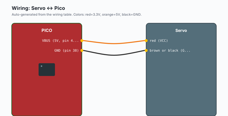
Servo red (VCC) -- Pico VBUS (5V, pin 40)
Servo brown or black (GND) -- Pico GND (pin 38)
Servo orange or yellow (signal) -- Pico GPIO 0 (pin 1)
GPIO 0 through GPIO 28 all work for servos. Avoid GPIO 26-28 if you are also using the ADC (those pins are ADC-capable and you lose analog reads). GPIO 15 is the only PWM-capable pin that overlaps with a boot pin; avoid it on the Pico W.
The code
MicroPython (Pico)
from machine import Pin, PWM

pwm = PWM(Pin(0))
pwm.freq(50)   # 50 Hz

# 0 degrees (1ms pulse = 5% duty cycle at 50Hz)
pwm.duty_u16(int(65535 * 0.05))

# 90 degrees (1.5ms pulse = 7.5% duty cycle)
pwm.duty_u16(int(65535 * 0.075))

# 180 degrees (2ms pulse = 10% duty cycle)
pwm.duty_u16(int(65535 * 0.10))
duty_u16 takes a value from 0 to 65535. The fraction times 65535 is the
duty cycle.
Arduino (Pico)
The Servo.h library that ships with the Arduino IDE works on the
Pico’s Arduino core. Same wiring, same code as the Uno.
#include <Servo.h>

Servo myServo;

void setup() {
  myServo.attach(0);   // GPIO 0 on the Pico
}

void loop() {
  for (int angle = 0; angle <= 180; angle++) {
    myServo.write(angle);
    delay(15);
  }
  for (int angle = 180; angle >= 0; angle--) {
    myServo.write(angle);
    delay(15);
  }
}
Servo.h on the Pico handles the 50 Hz PWM timing internally, the same
way it does on the Uno. The Pico has 8 PWM slices; Servo.h allocates
one per attached servo, so up to 8 servos on a Pico with this library
before you need an external driver like the PCA9685.
A cleaner servo library
The math above is fiddly. Wrap it in a helper:
from machine import Pin, PWM

class Servo:
    def __init__(self, pin):
        self.pwm = PWM(Pin(pin))
        self.pwm.freq(50)

    def write(self, angle):
        # Clamp to 0-180
        angle = max(0, min(180, angle))
        # Map 0-180 to 5-10% duty cycle
        duty = int(65535 * (0.05 + (angle / 180.0) * 0.05))
        self.pwm.duty_u16(duty)

servo = Servo(0)
servo.write(0)
time.sleep(1)
servo.write(90)
time.sleep(1)
servo.write(180)
This is the pattern I use in every Pico servo project.
A knob-controlled servo
Combine with an ADC reading:
from machine import Pin, PWM, ADC
import time

class Servo:
    def __init__(self, pin):
        self.pwm = PWM(Pin(pin))
        self.pwm.freq(50)

    def write(self, angle):
        angle = max(0, min(180, angle))
        duty = int(65535 * (0.05 + (angle / 180.0) * 0.05))
        self.pwm.duty_u16(duty)

servo = Servo(0)
pot = ADC(Pin(26))   # GP26 is ADC0

while True:
    raw = pot.read_u16()   # 0 to 65535
    angle = raw / 65535.0 * 180.0
    servo.write(angle)
    time.sleep(0.02)
Turn the pot, the servo follows. This is the foundation for “knob- controlled camera” and “knob-controlled valve.”
When the servo jitters
The three usual causes:
- Insufficient power. The SG90 draws 100-200 mA when moving. The Pico’s VBUS can supply about 500 mA. For multiple servos or larger servos, use an external 5V supply.
- Shared ground missing. If you are using an external supply, the Pico’s GND must be connected to the supply’s GND.
- Electrical noise. Add a 100uF capacitor across the servo’s power pins, close to the servo.
When the servo makes a clicking sound but does not move
- The signal wire is on the wrong pin. Double-check.
- The duty cycle is wrong. Verify with
pwm.duty_u16(...)print debug. - The servo is being asked to move past its physical range (e.g. 200 degrees). The library clamps to 180; without it, the servo can sit there buzzing.
Multiple servos
servos = [Servo(0), Servo(1), Servo(2), Servo(3)]

# Wave them back and forth
while True:
    for angle in range(0, 180, 5):
        for s in servos:
            s.write(angle)
        time.sleep_ms(20)
    for angle in range(180, 0, -5):
        for s in servos:
            s.write(angle)
        time.sleep_ms(20)
The Pico has 8 PWM-capable slices (16 channels). Each PWM slice can drive two outputs at the same frequency. For four servos, you can use two slices. For 16 servos, you need a PCA9685 driver over I2C.
Continuous rotation servos
A “continuous rotation” servo treats the duty cycle as speed and direction:
- 7.5% duty cycle: stop
- 10% duty cycle: full speed one direction
- 5% duty cycle: full speed the other direction
- 8.75% duty cycle: slow one direction
These are great for small wheeled robots. They have no position feedback, so you cannot tell where they are pointing, only how fast they are spinning.
What to build next
- A pan/tilt camera mount (two servos).
- A walking robot with 4-8 servos.
- A robotic arm with 4 servos and a gripper.
The robotic arm version is in the book Pico Robotics. The pan/tilt mount is one of the next tutorials on this site.