Arduino: use I2C to talk to sensors and displays
I2C is the two-wire protocol that connects most Arduino sensors. This tutorial covers the wiring, the address scan, and the most common gotchas.
I2C is the protocol that almost every modern Arduino sensor uses. Two wires (SDA and SCL), up to 127 devices on the same bus, and a standardized address scheme. Once you understand I2C, you can wire up an OLED display, a temperature sensor, an accelerometer, and a port expander on the same two pins.
This tutorial covers the protocol basics, the wiring, and the I2C scanner that will save you hours of debugging.
What you need
- Arduino (Uno, Nano, etc.)
- Any I2C device (BME280, OLED display, MPU6050, etc.)
- Jumper wires
Wiring
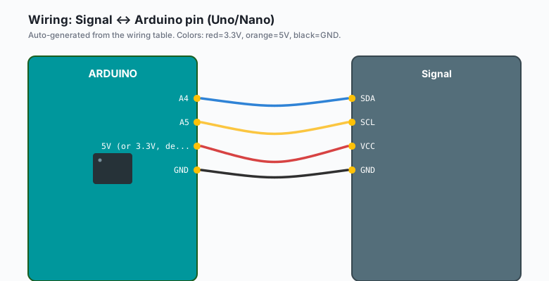
I2C has four wires total:
| Signal | Arduino pin (Uno/Nano) |
|---|---|
SDA | A4 |
SCL | A5 |
VCC | 5V (or 3.3V, depending on device) |
GND | GND |
For the Mega, SDA is pin 20 and SCL is pin 21. For the Nano 33 IoT, SDA is pin A4 and SCL is pin A5 (same as the Uno, despite the different name).
Most breakout boards (e.g. Adafruit, SparkFun) have pull-up resistors already. If you are using bare sensors without a breakout, add 4.7k pull-ups from SDA to VCC and SCL to VCC.
The I2C scanner
When a sensor does not respond, the first thing I run is the I2C scanner. This sketch tells you every address on the bus:
Arduino (Uno, Nano, Mega)
#include <Wire.h>

void setup() {
  Serial.begin(9600);
  Wire.begin();
  Serial.println("I2C Scanner");
}

void loop() {
  for (byte addr = 1; addr < 127; addr++) {
    Wire.beginTransmission(addr);
    if (Wire.endTransmission() == 0) {
      Serial.print("Device found at 0x");
      if (addr < 16) Serial.print("0");
      Serial.println(addr, HEX);
    }
  }
  Serial.println("---");
  delay(2000);
}
Upload it. Open Serial Monitor. You should see the address(es) of any connected I2C device.
ESP32 (Arduino)
#include <Wire.h>

void setup() {
  Serial.begin(115200);
  Wire.begin(21, 22);   // SDA, SCL on the ESP32
  Serial.println("I2C Scanner");
}

void loop() {
  for (byte addr = 1; addr < 127; addr++) {
    Wire.beginTransmission(addr);
    if (Wire.endTransmission() == 0) {
      Serial.print("Device found at 0x");
      if (addr < 16) Serial.print("0");
      Serial.println(addr, HEX);
    }
  }
  Serial.println("---");
  delay(2000);
}
Same code, but you usually need to pass the SDA/SCL pins to Wire.begin()
on the ESP32 (defaults to GPIO 21/22 on most cores).
MicroPython (ESP32 or Pico)
from machine import I2C, Pin

# ESP32: GPIO 21 (SDA), 22 (SCL)
# Pico: GPIO 0 (SDA), 1 (SCL)
i2c = I2C(0, scl=Pin(22), sda=Pin(21), freq=100_000)

print('I2C devices:')
for addr in i2c.scan():
    print(f'  0x{addr:02X}')
This is the equivalent of the I2C scanner: it lists every address on the
bus. i2c.scan() returns a list of integers; the f-string formats each
as a 2-digit hex address.
Raspberry Pi Python
import smbus2

bus = smbus2.SMBus(1)   # /dev/i2c-1 on most Pi images

print('I2C devices:')
for addr in range(0x03, 0x78):
    try:
        bus.read_byte(addr)
        print(f'  0x{addr:02X}')
    except OSError:
        pass
Enable I2C on the Pi first: sudo raspi-config >> Interface Options >>
I2C >> Enable. Then pip3 install smbus2.
Common addresses:
- 0x3C or 0x3D: OLED displays
- 0x76 or 0x77: BME280, BMP280
- 0x68: MPU6050, DS3231 RTC
- 0x57: AT24C32 EEPROM
If you see no devices, the wiring is wrong, the device is unpowered, or the device uses a different address than you expected.
Reading from a BME280 example
Once you know the address, you can talk to it.
Arduino (Uno, Nano, Mega)
#include <Wire.h>
#include <Adafruit_Sensor.h>
#include <Adafruit_BME280.h>

Adafruit_BME280 bme;

void setup() {
  Serial.begin(9600);
  Wire.begin();
  if (!bme.begin(0x76)) {   // change to 0x77 if scanner found it there
    Serial.println("Could not find BME280");
    while (1);
  }
}

void loop() {
  Serial.print("Temp: ");
  Serial.print(bme.readTemperature());
  Serial.print(" C, Humidity: ");
  Serial.print(bme.readHumidity());
  Serial.print(" %, Pressure: ");
  Serial.print(bme.readPressure() / 100.0);
  Serial.println(" hPa");
  delay(2000);
}
This is the canonical pattern: Wire.begin(), library constructor with
the address, then call the library’s methods.
ESP32 (Arduino)
#include <Wire.h>
#include <Adafruit_Sensor.h>
#include <Adafruit_BME280.h>

Adafruit_BME280 bme;

void setup() {
  Serial.begin(115200);
  Wire.begin(21, 22);   // SDA, SCL on the ESP32
  if (!bme.begin(0x76)) {
    Serial.println("Could not find BME280");
    while (1);
  }
}

void loop() {
  Serial.print("Temp: ");
  Serial.print(bme.readTemperature());
  Serial.print(" C, Humidity: ");
  Serial.print(bme.readHumidity());
  Serial.print(" %, Pressure: ");
  Serial.print(bme.readPressure() / 100.0);
  Serial.println(" hPa");
  delay(2000);
}
Same library, same code. The ESP32 version just passes the I2C pins explicitly and uses a faster serial baud.
MicroPython (ESP32 or Pico)
from machine import I2C, Pin
import time

i2c = I2C(0, scl=Pin(22), sda=Pin(21), freq=100_000)

BME280_ADDR = 0x76

def read_bme280():
    data = i2c.readfrom_mem(BME280_ADDR, 0xF7, 8)
    press_raw = (data[0] << 12) | (data[1] << 4) | (data[2] >> 4)
    temp_raw  = (data[3] << 12) | (data[4] << 4) | (data[5] >> 4)
    hum_raw   = (data[6] << 8)  | data[7]
    return temp_raw / 5120.0, hum_raw / 1024.0, press_raw / 256.0 / 100.0

print('BME280 reading (raw, not calibrated)')
while True:
    t, h, p = read_bme280()
    print(f'{t:.2f} C, {h:.2f} %, {p:.2f} hPa')
    time.sleep(2)
For calibrated readings on MicroPython, install the official BME280
driver: mip install bme280 on the Pico, or copy bme280.py from
https://github.com/micropython-IMU/micropython-bme280.
Raspberry Pi Python
Install the proper driver:
pip3 install bme280 smbus2Then:
from smbus2 import SMBus
import bme280
import time

bus = SMBus(1)
addr = 0x76

print('BME280 ready')
while True:
    data = bme280.sample(bus, addr)
    print(f'{data.temperature:.2f} C, {data.humidity:.2f} %, {data.pressure:.2f} hPa')
    time.sleep(2)
bme280.sample() returns a BME280Reading with temperature,
humidity, pressure, and timestamp fields. The driver handles all
the calibration math.
Why I2C devices can have two addresses
Most I2C chips have an “address select” pin. The BME280’s SDO pin determines whether the I2C address is 0x76 (SDO to GND) or 0x77 (SDO to VCC). Some boards hard-wire one or the other. If your scanner finds 0x77 and your code says 0x76, you have the wrong address. Fix the code.
The bus speed
The default I2C speed is 100 kHz. Most devices support 400 kHz (called “Fast Mode”). To speed it up:
Wire.setClock(400000);Some devices only work at 100 kHz (older sensors, some EEPROMs). If a device stops responding after you bump the speed, drop it back to 100 kHz.
Common gotchas
- No pull-ups. Bare I2C devices need external pull-ups. Breakout boards usually have them.
- Mixed voltage. 5V Arduino talking to 3.3V sensor will eventually fry the sensor. Use a level shifter, or pick a sensor with a 5V-tolerant version (e.g. the Adafruit BME280 board has a 3.3V regulator and level-shifted I2C lines, so it works on 5V Arduinos).
- Two devices with the same address. You cannot have two devices at the same address on the same bus unless one has a way to change its address. For the rare case you do, use an I2C multiplexer (TCA9548A).
- Wire length. I2C is meant for short distances (under 1 m on a hobbyist setup, much less at 400 kHz). For longer runs, use RS-485 or CAN, not I2C.
Reading from multiple devices
The pattern is the same. Construct each device with its address:
Adafruit_BME280 indoor;     // 0x76
Adafruit_BME280 outdoor;    // 0x77
Adafruit_SSD1306 display;   // 0x3C

void setup() {
  Wire.begin();
  indoor.begin(0x76);
  outdoor.begin(0x77);
  display.begin(SSD1306_SWITCHCAPVCC, 0x3C);
}
All three live on the same two wires. The library handles the rest.
When I2C hangs
If Wire.endTransmission() never returns, or the bus is stuck low, the
most common cause is a missing pull-up. The SDA or SCL line is floating
and the device is holding it low waiting for an ACK that never comes.
Fix: power cycle the Arduino (the bus reset is hardware-level). Then add the missing pull-ups.
For a software reset of the bus:
Wire.end();
delay(100);
Wire.begin();
But the hardware reset is more reliable.
What to build next
- An OLED display showing sensor data (I2C display + I2C sensor).
- A weather station with multiple I2C sensors.
- An I2C-controlled motor driver (e.g. DRV2605 haptic motor controller).
The OLED weather station is one of the next tutorials on this site. The multi-sensor version is in the book Arduino Sensors.