Pico: use PIO to drive WS2812B LEDs (NeoPixels)
The Pico's Programmable I/O can drive WS2812B LEDs without blocking your code. A reusable PIO program you can drop into any project.
The Pico has Programmable I/O (PIO), which is the killer feature for LED projects. PIO is a tiny co-processor that handles bit-banged protocols in hardware, so your MicroPython script does not get blocked while the LEDs are updating.
This tutorial covers the PIO program for WS2812B, how to wire it up, and how to drive a strip from MicroPython.
What you need
- Raspberry Pi Pico
- WS2812B strip (any length)
- 330 ohm resistor on the data line
- 470uF capacitor across the strip’s power pads
- 5V power supply rated for the strip
Wiring
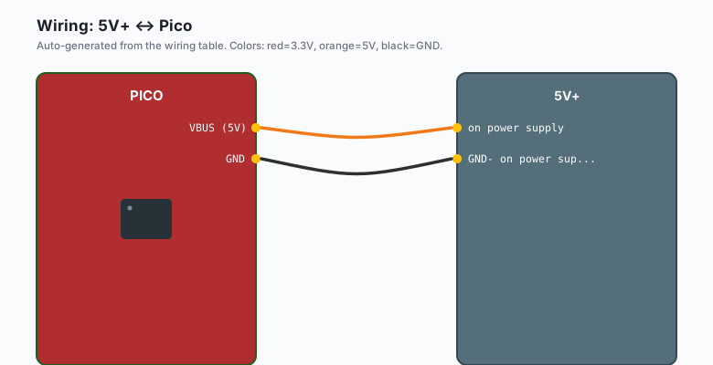
Pico VBUS (5V)  ---- 5V+ on power supply
                ---- 5V on WS2812B strip
Pico GND        ---- GND- on power supply
                ---- GND on WS2812B strip
Pico GPIO 0 --[330R]-- DIN on WS2812B strip
The resistor and capacitor are not optional for reliability.
The code
MicroPython (Pico)
Save this as ws2812b.py on the Pico:
import rp2
from machine import Pin
import time

@rp2.asm_pio(sideset_init=rp2.PIO.OUT_LOW, out_shiftdir=rp2.PIO.SHIFT_LEFT,
             autopull=True, pull_thresh=24)
def ws2812():
    T1 = 2
    T2 = 5
    T3 = 3
    wrap_target()
    label("bitloop")
    out(x, 1)               .side(0)    [T3 - 1]
    jmp(x_not_y, "do_zero") .side(1)    [T1 - 1]
    jmp("do_one")           .side(1)    [T2 - 1]
    label("do_zero")
    nop()                   .side(0)    [T2 - 1]
    label("do_one")
    wrap()

class WS2812B:
    def __init__(self, num_leds, pin):
        self.num_leds = num_leds
        self.sm = rp2.StateMachine(0, ws2812, freq=8_000_000,
                                    sideset_base=Pin(pin))
        self.sm.active(1)
        self.buf = bytearray(num_leds * 3)

    def __setitem__(self, index, color):
        offset = index * 3
        self.buf[offset] = (color >> 16) & 0xff   # red
        self.buf[offset + 1] = (color >> 8) & 0xff  # green
        self.buf[offset + 2] = color & 0xff         # blue

    def __getitem__(self, index):
        offset = index * 3
        return (self.buf[offset] << 16) | (self.buf[offset + 1] << 8) | self.buf[offset + 2]

    def fill(self, color):
        for i in range(self.num_leds):
            self[i] = color

    def write(self):
        self.sm.put(self.buf, 8)

# Usage:
NUM_LEDS = 60
strip = WS2812B(NUM_LEDS, 0)

def wheel(pos):
    if pos < 85:
        return (255 - pos * 3, pos * 3, 0)
    elif pos < 170:
        pos -= 85
        return (0, 255 - pos * 3, pos * 3)
    else:
        pos -= 170
        return (pos * 3, 0, 255 - pos * 3)

while True:
    for j in range(255):
        for i in range(NUM_LEDS):
            strip[i] = wheel((i * 256 // NUM_LEDS + j) & 255)
        strip.write()
        time.sleep_ms(10)
Run it. The strip should show a rainbow cycle.
Arduino (Pico)
The Pico’s Arduino core has its own PIO API. Most projects do not need
PIO directly: the Adafruit NeoPixel library handles the WS2812B
protocol with regular GPIO bit-banging, and it works on the Pico out of
the box. Install it through the Arduino IDE
(Sketch >> Include Library >> Manage Libraries >> search
Adafruit NeoPixel).
The Arduino code is the same as the ESP32 and Uno versions. Pin
numbers in the Pico Arduino core map to the GPIO number directly, so
PIN 0 is GPIO 0.
#include <Adafruit_NeoPixel.h>

#define LED_PIN    0
#define NUM_LEDS   60

Adafruit_NeoPixel strip(NUM_LEDS, LED_PIN, NEO_GRB + NEO_KHZ800);

uint32_t wheel(byte pos) {
  if (pos < 85) {
    return strip.Color(255 - pos * 3, pos * 3, 0);
  } else if (pos < 170) {
    pos -= 85;
    return strip.Color(0, 255 - pos * 3, pos * 3);
  } else {
    pos -= 170;
    return strip.Color(pos * 3, 0, 255 - pos * 3);
  }
}

void setup() {
  strip.begin();
  strip.show();
}

void loop() {
  for (long j = 0; j < 256; j++) {
    for (int i = 0; i < NUM_LEDS; i++) {
      strip.setPixelColor(i, wheel((i * 256 / NUM_LEDS + j) & 255));
    }
    strip.show();
    delay(10);
  }
}
The Adafruit NeoPixel library uses bit-banging, not PIO. It is
accurate enough for short to medium strips (about 500 LEDs). For
larger strips or for freeing the CPU during updates, you would write a
PIO program directly via rp2040.pio headers in the Pico Arduino core.
That is more advanced; the library version is fine for most projects.
How PIO works
PIO is a tiny state machine that runs on the chip separately from the
main CPU. You write a small assembly program (the @rp2.asm_pio()
function) that describes what to do with one or two GPIO pins. The Pico’s
hardware runs this program in parallel with your MicroPython code.
For the WS2812B protocol:
- Each LED needs 24 bits (8 bits per color).
- Each bit is encoded by the duration of the high signal: 0.4 us high for a “0” bit, 0.8 us high for a “1” bit.
- The total period for one bit is 1.25 us.
The PIO program above runs at 8 MHz, with timing values tuned to produce
the right pulse widths. The out instruction pulls a bit from the FIFO
queue, and the side-set pin toggles to produce the protocol.
Why PIO is better than bit-banging
Without PIO, you would have to toggle the GPIO pin at exactly the right microseconds in MicroPython. With PIO, the hardware does it, freeing the CPU for your application code.
Practical differences:
- CPU usage: 0% with PIO, 80%+ with bit-banging on a 60-LED update.
- Timing accuracy: PIO is exact. Bit-banging has jitter that causes occasional glitches.
- Multi-tasking: with PIO, you can run other code while the LEDs update. With bit-banging, your code is blocked.
For a 60-LED strip, the difference is huge. For 8 LEDs, either works.
Color order
WS2812Bs come in two color orders: GRB (most common) and RGB. The library above assumes GRB. If your colors are wrong (e.g. you ask for red and get green), swap the byte order:
def __setitem__(self, index, color):
    offset = index * 3
    self.buf[offset] = (color >> 8) & 0xff    # green first
    self.buf[offset + 1] = (color >> 16) & 0xff  # then red
    self.buf[offset + 2] = color & 0xff        # then blue
The WS2812B datasheet says GRB, but some strips are labeled RGB or BGR. When in doubt, test with a single color and check what comes out.
Brightness control
The strip uses 8 bits per color (0-255). For indoor eye-candy, drop the max to 60 or so to save power and avoid blinding yourself:
def brightness(color, factor):
    r = (color >> 16) & 0xff
    g = (color >> 8) & 0xff
    b = color & 0xff
    factor = factor / 255.0
    return (int(r * factor) << 16) | (int(g * factor) << 8) | int(b * factor)

# Usage:
strip[i] = brightness(wheel(...), 80)   # ~30% brightness
What to build next
- A music-reactive LED strip (add a microphone and FFT).
- An 8x8 or 16x16 LED matrix and run text across it.
- A “fire” effect with random red/orange flickering.
The matrix version is in the book Pico LED Projects. The music-reactive strip is one of the next tutorials on this site.