ESP32: negotiate USB-C PD voltages with a trigger board
Get 5V, 9V, 12V, 15V, or 20V out of any USB-C charger with a FUSB302 or HW-715 trigger board. The right power source when you need 12V from a USB-C brick.
USB-C Power Delivery is the standard that lets a single USB-C charger deliver 5V, 9V, 12V, 15V, or 20V at up to 100W. Your laptop uses it to charge. So does your phone, your monitor, and most modern USB-C devices. With a PD trigger board, your ESP32 project can also use it: ask the charger for 12V, and you get 12V on a barrel jack or screw terminal, with no wall wart.
The trigger board is the small chip (FUSB302) or module (HW-715) that sits between the USB-C connector and your project. It does the PD negotiation with the charger, and outputs the requested voltage on a separate pin. Your ESP32 can either pre-configure the trigger (so it always asks for the same voltage) or talk to the trigger over I2C and request different voltages on demand.
I use these for projects that need more than 5V: LED strips, 12V fans, small motors, anything that previously needed a wall wart. The USB-C brick is the supply; the trigger board is the converter.
What you need
- ESP32 dev board (or Arduino Uno/Nano)
- USB-C PD trigger board. Two common options:
- FUSB302 bare chip on a breakout (e.g. the Adafruit FUSB302 board; about $10)
- HW-715 module (the cheap eBay/AliExpress option; about $3-5). Pick the “HW-715 PD/QC trigger” version, not the decoy-only versions.
- USB-C cable (data + power, not charge-only)
- USB-C charger or power bank that supports PD (any Apple, Anker, Aukey, or Raspberry Pi 4+ supply)
The HW-715 has a default requested voltage set by solder jumpers on the back. If you want the ESP32 to control the voltage dynamically, get the FUSB302 version with I2C.
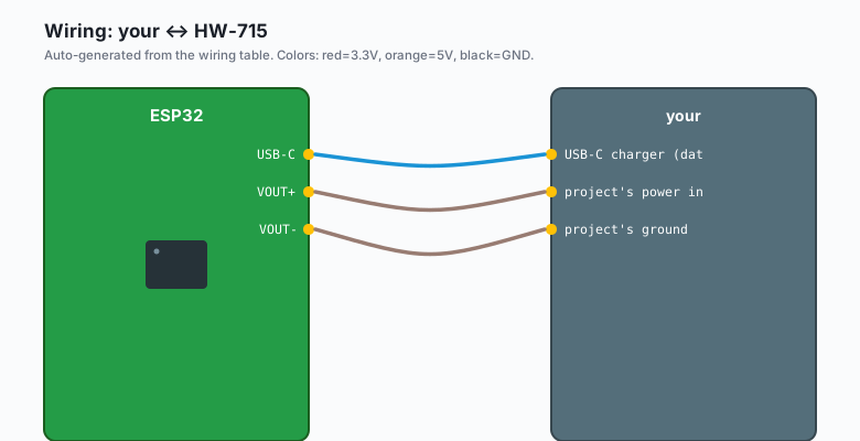
Wiring (HW-715, fixed voltage)
The HW-715 has a few solder jumpers on the back that pick the requested voltage. The default is usually 12V. To change it, bridge the corresponding pads with solder.
HW-715 USB-C  -- your USB-C charger (data + power cable)
HW-715 VOUT+  -- your project's power input (12V nominal)
HW-715 VOUT-  -- your project's ground
That is the entire wiring for the trigger side. The ESP32 does not need to do anything; the trigger and charger handle the negotiation in hardware.
Wiring (FUSB302, ESP32-controlled)
The Adafruit FUSB302 board talks to the ESP32 over I2C.
FUSB302 VCC   -- ESP32 3.3V
FUSB302 GND   -- ESP32 GND
FUSB302 SDA   -- ESP32 GPIO 21
FUSB302 SCL   -- ESP32 GPIO 22
FUSB302 INT   -- ESP32 GPIO 4   (optional; interrupt pin)
FUSB302 CC1, CC2 -- USB-C connector (CC1 and CC2 pins on the
                    USB-C breakout)
FUSB302 VBUS  -- USB-C VBUS (the 5V supply pin)
You also need a USB-C breakout to bring the CC1, CC2, and VBUS pins out to a header. The trigger chip does the PD negotiation over the CC lines.
Install libraries
Sketch >> Include Library >> Manage Libraries >> search
FUSB302 (or USB Power Delivery for the more capable
library). Install it.
The bare FUSB302 needs a lower-level library that handles the PD state machine. The common picks are:
- FUSB302 by Joseph Duchesne (basic, just for triggering)
- USB Power Delivery by Joshua Bernardino (full PD stack, can negotiate any voltage on any port)
For 90% of projects, the basic FUSB302 library is enough: you request a fixed voltage (say 12V), the chip handles the rest.
The code (FUSB302, request 12V)
ESP32 (Arduino)
#include <Wire.h>
#include "FUSB302.h"

FUSB302 fusb;

void setup() {
  Serial.begin(115200);
  Wire.begin();
  Wire.setClock(400000);

  if (!fusb.begin()) {
    Serial.println("FUSB302 not found");
    while (1);
  }

  Serial.println("FUSB302 ready");
  Serial.print("Source PDO count: ");
  Serial.println(fusb.getSourcePDOCount());

  // Request 12V at 1.5A (18W) from the source
  if (fusb.requestPDO(2, 1500)) {   // PDO index 2 is 12V on most sources
    Serial.println("Negotiated 12V");
  } else {
    Serial.println("Negotiation failed, falling back to 5V");
  }
}

void loop() {
  // The FUSB302 holds the negotiation; nothing to do.
  // If the source disconnects, the INT pin goes LOW.
  delay(1000);
}
The requestPDO(index, current_mA) call sends the request to the
charger. The index refers to the Power Data Object the source
advertised; for most USB-C chargers, index 0 is 5V, index 1 is 9V,
index 2 is 12V, index 3 is 15V, index 4 is 20V. The exact ordering
depends on the charger.
Arduino (Uno, Nano, Mega)
#include <Wire.h>
#include "FUSB302.h"

FUSB302 fusb;

void setup() {
  Serial.begin(9600);
  Wire.begin();
  Wire.setClock(400000);

  fusb.begin();

  Serial.print("Source PDO count: ");
  Serial.println(fusb.getSourcePDOCount());

  if (fusb.requestPDO(2, 1500)) {
    Serial.println("12V negotiated");
  }
}

void loop() {}
On the 5V Arduino, the I2C pull-ups on the FUSB302 board are usually 3.3V. That works with the Arduino’s 5V I2C because the FUSB302 is 3.3V tolerant on its SDA/SCL pins.
Reading the negotiated voltage
The FUSB302 can also read back the actual voltage the source is providing. Useful for confirming the negotiation worked:
uint16_t voltage_mV = fusb.getVBUSVoltage();
Serial.print("VBUS: ");
Serial.print(voltage_mV / 1000.0);
Serial.println(" V");
The chip measures VBUS through an internal ADC. The reading is accurate to about ±5%, which is enough for “is it 5V or 12V.”
Why a trigger board, not just a USB-C connector
A plain USB-C connector passes 5V through. That is fine for a phone charger, but most ESP32 projects need either 3.3V (which the on-board regulator handles) or 12V (for an LED strip, a fan, a motor). A USB-C connector cannot give you 12V; the source provides 5V unless the device asks for more over the CC lines.
The trigger board is the part that asks. Without it, you are stuck with 5V.
The HW-715 vs. the FUSB302
The HW-715 is a fixed-voltage trigger. The voltage is set by solder jumpers on the back; the ESP32 has no control. It is cheaper ($3-5) and simpler (no code, no I2C). Use it when the project always needs the same voltage (e.g. a 12V LED strip).
The FUSB302 is the I2C-controlled trigger. The ESP32 requests the voltage at runtime. It is more expensive ($10 for the Adafruit board) and needs code, but it lets the project change voltages on demand (e.g. “12V when the LED strip is on, 5V otherwise” for power saving).
Power and the ESP32’s regulator
The 12V (or 20V) from the trigger is way too high for the ESP32’s on-board regulator (which expects 5-12V max). The right pattern:
- Trigger outputs 12V to the project’s main power rail.
- The main power rail feeds the LED strip, fan, or motor.
- A separate buck converter drops 12V to 5V for the ESP32’s USB or VIN pin.
- The ESP32’s on-board regulator drops 5V to 3.3V for itself.
For 5V-only projects, the trigger outputs 5V and the buck converter is not needed.
What you learned
- USB-C PD lets a single charger deliver 5V-20V.
- The trigger board does the negotiation; the ESP32 can either pre-configure the trigger (HW-715) or control it over I2C (FUSB302).
- The negotiated voltage is read back through the FUSB302’s internal ADC.
- For 12V/20V projects, you need a buck converter to drop the voltage to 5V for the ESP32.
When something breaks
- No negotiation, charger stays at 5V. USB-C cable is charge- only. Replace with a data + power cable. The CC lines need to be connected for PD to work.
- FUSB302 not found on I2C scan. Wrong I2C address (the Adafruit board is 0x22 by default; some clones are 0x23). Run a scanner and update.
- Negotiated 5V when you wanted 12V. The source does not
advertise 12V. Some cheap chargers only do 5V + 9V; some only
do 5V + 20V. Check with
fusb.getSourcePDOCount()and print each PDO. - ESP32 resets when the trigger fires. The 12V rail is sagging under load. Add a 100uF capacitor on the 12V rail, or use a heavier-gauge wire.
- Negotiation works, but the load does not turn on. VBUS enable pin not driven. Some FUSB302 boards have a separate VBUS load switch that must be enabled by a GPIO. Check the board’s schematic.
What to build next
- The 18650 with TP4056 tutorial is the right pick for battery-powered projects.
- The relay module tutorial combined with this lets you switch 12V loads using a USB-C brick as the supply.
- The book ESP32 in Production has a 12V LED strip controller that uses the FUSB302 to negotiate 12V from a 65W USB-C laptop charger.