ESP32: timer interrupts and why loop() timing drifts
Use the ESP32's hardware timers for interrupt-driven timing, understand why millis() and delay() drift under load, and stop your blinking LED from wandering.
You wire a blink sketch with delay(1000), then add a sensor read, then
an OLED update, then an MQTT publish, and suddenly the “1 second” LED
blinks every 1.4 seconds and you cannot say where the time went. That
drift is not a bug in your code, it is a property of cooperative
looping: loop() only runs your timing check when it is not busy doing
something else. The fix is to let the hardware keep time. The ESP32 has
four hardware timer peripherals that fire interrupts whether your code
is busy or not, and this tutorial wires one up, explains the two
correct ways to use it, and shows exactly where loop-based timing loses
seconds.
The trap I hit: I put Serial.println() inside a timer interrupt (ISR
in short, interrupt service routine) and the ESP32 crashed with a
Guru Meditation error about a watchdog, repeatedly, with no obvious
cause. Printing from an ISR is one of several things that are illegal
there, and the ESP32 core’s crash messages do not exactly walk you back
to the cause. The rules are short (keep the ISR tiny, no Serial, no
delay, only touch data marked volatile, prefer setting a flag over
doing work), and once they are habits the timers are the most useful
peripheral on the chip.
What you need
Needed
- ESP32 dev board (e.g. an ESP32-WROOM-32 devkit): the chip with the timers (the classic WROOM has 4 general-purpose hardware timers)
- Onboard LED (none needed, GPIO 2 blinks on most devkits) or one 5mm LED + 220 ohm resistor: the visual output you time
- 2x jumper wires plus breadboard: only if you use an external LED
Nice to have
- A second ESP32 acting as a receiver (or the logic analyzer tutorial’s gear): measures the real intervals your first board produces
- Multimeter: checks the LED resistor math before power-up
- Wire stripper: for the LED legs if you go external
- The oscilloscope tutorial’s cheap scope: the honest way to see drift and jitter as a picture instead of a suspicion
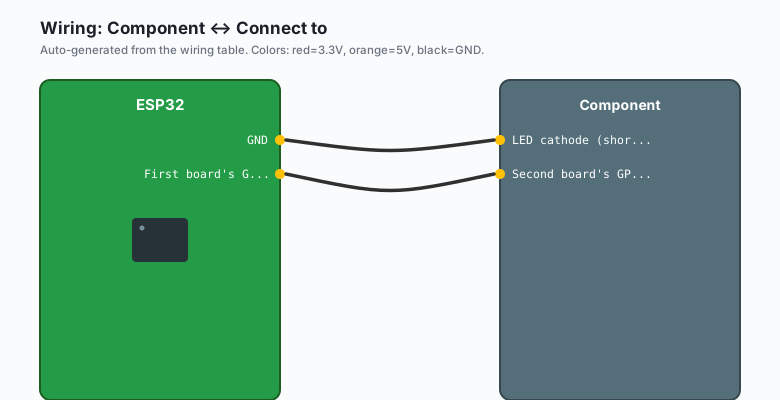
Wiring
External LED version (skip if you use the onboard LED on GPIO 2):
| Component | Connect to |
|---|---|
| LED anode (long leg) | GPIO 2 through a 220 ohm resistor |
| LED cathode (short leg) | GND |
Second board’s GPIO 2 (drift probe) | First board’s GPIO 2 (GND to GND), optional |
GPIO 2 is safe on every common devkit and already wired to an onboard LED, which is why this tutorial uses it. Avoid GPIO 6-11 (flash chip) and the input-only pins (34, 35, 36, 39) for outputs.
Install
Nothing to install. The timer API (hw_timer_t) ships with the ESP32
Arduino core. (The Arduino-ESP32 core changed this API at version 3.x:
timerBegin takes fewer arguments and timerAttachInterrupt dropped
the edge parameter. The code below is written for core 3.x, with the
2.x differences noted so you can adapt in one pass.)
The code
The mental model: a hardware timer counts clock ticks on its own,
independent of your code. When the count hits the value you set, the
peripheral fires an interrupt and the CPU jumps to your ISR function
no matter what loop() was doing, then jumps back. Your ISR should do
almost nothing (set a flag or toggle a pin) and let loop() handle
anything with real work in it. That split is the whole design pattern.
#include <Arduino.h>

#define LED_PIN 2

hw_timer_t* timer = NULL;
volatile bool tickFlag = false;      // volatile: ISR writes, loop reads
volatile uint32_t tickCount = 0;

// The ISR: minimal by law, not by style.
// IRAM_ATTR keeps this code in fast internal RAM so it runs even while
// flash is busy (e.g. during an SPI flash write from the other core).
void IRAM_ATTR onTimer() {
  tickFlag = true;                   // set a flag, nothing else
  tickCount++;
  // digitalWrite(LED_PIN, !digitalRead(LED_PIN));  // legal, pin-only
  // Serial.println("tick");   // ILLEGAL: crash (uart not ISR-safe)
  // delay(1);                 // ILLEGAL: blocks inside the ISR
}

void setup() {
  Serial.begin(115200);
  pinMode(LED_PIN, OUTPUT);

  // Core 3.x API:
  timer = timerBegin(1000000);           // 1 MHz tick: 1 tick = 1 us
  timerAttachInterrupt(timer, &onTimer);
  timerAlarm(timer, 1000000, true, 0);   // 1,000,000 us = 1 s, auto-reload

  // Core 2.x API, if you are on the older core:
  //   timer = timerBegin(0, 80, true);            // timer 0, 80 MHz/80 = 1 MHz
  //   timerAttachInterrupt(timer, &onTimer, true);
  //   timerAlarmWrite(timer, 1000000, true);      // 1 s, auto-reload
  //   timerAlarmEnable(timer);
}

void loop() {
  if (tickFlag) {
    tickFlag = false;                // consume the flag
    digitalWrite(LED_PIN, !digitalRead(LED_PIN));

    // Real work (printing, network, sensors) lives HERE, not in the ISR
    static uint32_t lastPrint = 0;
    uint32_t now = millis();
    if (now - lastPrint >= 5000) {
      lastPrint = now;
      Serial.print("ticks: "); Serial.println(tickCount);
    }
  }

  // loop() can now do ANYTHING slow and blocking without hurting the
  // 1-second LED timing. Try adding delay(3000) right here and watch
  // the LED stay on schedule.
}
Three details that carry the design:
volatileis not decoration. Without it the compiler may cache the flag in a register andloop()never sees the ISR’s write. Every variable shared between an ISR and normal code getsvolatile, and anything wider than the CPU’s word size (e.g. a 64-bit counter) also needsnoInterrupts()/interrupts()around reads inloop().IRAM_ATTRis not decoration either. ISRs must live in internal RAM; without it the first flash operation that lands while the ISR is called crashes the chip.- The auto-reload parameter (
true) is what makes the timer periodic. Withfalseit fires once and stops, which is the right choice for one-shot timeouts (e.g. a sensor that must answer within 50 ms).
Why loop() timing drifts: the honest accounting
A millis()-based blinker (if (millis() - last >= 1000) { work; last = millis(); }) is fine on an idle chip. The drift arrives with load,
and each contributor has a name:
- Variable work in loop(). An MQTT publish takes 30 ms on a good network and 400 ms on a bad one. Your 1-second loop becomes “1 second plus whatever the work took” (e.g. 1.4 s with Wi-Fi retries).
- The
last = millis()reset. Checkingmillis()again after the work compounds every cycle’s slop instead of cancelling it. - Blocking libraries. Some drivers (certain sensor libs, SD card
writes) disable interrupts internally for stretches;
millis()itself can lose milliseconds there, which surprises people. delay()anywhere. Adelay(3000)in one branch of loop() makes every other timing check in loop() late by up to 3 seconds.
The hardware timer fixes all four at once: the interval is generated by a peripheral counting microseconds, not by your code getting around to checking. Jitter in the LED toggle becomes a few microseconds (the ISR latency), not hundreds of milliseconds.
Where a hardware timer is the wrong tool
- Network and sensor work. Keep it in loop() or a FreeRTOS task; the ISR only sets the flag.
- Anything that can wait 1 ms. The FreeRTOS tick and
vTaskDelayUntil()give you scheduling with none of the ISR rules (the multitasking tutorials cover that path). - Precision below a few microseconds. The timer interrupt latency is real; for pin-perfect pulse generation use the LEDC (PWM) peripheral or the RMT peripheral instead.
What you learned
- The ESP32 has four hardware timers that fire interrupts on their own
schedule, independent of whatever
loop()is doing. - An ISR must be tiny: no Serial, no delay,
volatileon shared data,IRAM_ATTRon the function, flag-in-ISR / work-in-loop as the pattern. millis()-based timing drifts under load because loop() only checks the clock when it is free; a hardware timer does not have that problem.- The timer API differs between Arduino-ESP32 core 2.x and 3.x; the argument shapes changed but the pattern did not.
When something breaks
- Guru Meditation Error / WDT reset after adding a timer. The ISR
is doing illegal work (Serial, delay, allocating memory, calling a
library). Strip the ISR down to flag-setting and pin writes only,
then add work back in
loop()where it belongs. A watchdog reset that namesesp_timerortask_wdtalmost always points at a fat ISR. - Flag never becomes true, LED never blinks. The alarm never fired:
check
timerAlarm()(3.x) ortimerAlarmEnable()(2.x) is actually called, and confirm the divider math (an 80 MHz clock with divider 80 is 1 MHz, so an alarm value of 1,000,000 is 1 second; people set 1000000 expecting 1 ms and get 1 s). loop()misses ticks or the counter skips.tickFlagis notvolatile, ortickCountoverflows a type too small for it (useuint32_tat minimum). If multiple ISR-shared variables matter together, wrap theloop()-side read innoInterrupts()/interrupts().- Timing is exact for minutes, then walks. You are measuring with
millis()against a timer: fine, but if the timer itself seems to drift it is usually crystal vs internal RC clock differences across two boards (e.g. one board 20 ppm fast). Two ESP32s never agree exactly; sync over NTP or MQTT instead of expecting it. - Crashes only under Wi-Fi load. The ISR and the Wi-Fi driver are
fighting for flash time: confirm
IRAM_ATTRon the ISR, and if you call any function from it, make sure that function (and what it calls) is also in IRAM. The safe ISR touches nothing butvolatilescalars and GPIO. - Second board sees jitter of a few hundred microseconds. That is the interrupt latency plus FreeRTOS scheduling on top; it is normal. If you need nanosecond-grade edges, that is a job for the RMT or LEDC peripherals, not a CPU-serviced interrupt.
What to build next
- The PWM with LEDC tutorial is the hardware-native way to generate exact waveforms (e.g. a 25 kHz fan PWM) with zero CPU involvement.
- The deep sleep tutorial is the timing story for battery devices: when the timer is the only thing awake, the hardware timer (or the RTC timer) wakes the chip on schedule.
- The mDNS tutorial and the MQTT publish/subscribe tutorial both benefit from timer-driven publish intervals: steady, drift-free reporting no matter what else the sketch handles.
- The web socket server tutorial pushes live dashboards, and a timer interrupt is what keeps the push interval honest when clients get slow (the watchdog timer tutorial on the Arduino side covers the “my loop hung” cousin of this problem).