ESP32: measure water quality (TDS) with the analog TDS sensor
Wire the analog TDS sensor module to an ESP32, convert ADC counts to ppm with temperature compensation, and calibrate against a known solution instead of guessing.
The TDS sensor is the cheapest honest answer to “is this water getting dirtier over time.” TDS stands for total dissolved solids (the fertilizer salts, minerals, and general junk dissolved in water, measured in ppm, parts per million). It will not tell you the water is safe to drink, and it will not detect bacteria or lead. What it does tell you, cheaply and continuously, is whether the number moved from yesterday: hydroponic reservoirs, aquarium top-offs, reverse-osmosis filters, and plant watering cans all get real value from that one number. This tutorial wires the DFRobot-style analog TDS module to an ESP32, compensates for water temperature, and calibrates it so the ppm number means something.
The trap I hit: my first readings were almost double the hand-held TDS meter I was calibrating against. The sensor was fine; the problem was porting the Arduino sample code as-is. DFRobot’s example assumes a 5.0V ADC reference (an Uno), but the ESP32’s ADC is 3.3V-referenced with 12-bit resolution, so every voltage I converted was scaled wrong. The module’s output tops out at 2.3V (fixed by its onboard 3.0V regulator), which conveniently sits inside the ESP32 ADC’s good range. The second trap: on the ESP32, ADC2 pins stop working entirely once Wi-Fi turns on, and the probe was wired to an ADC2 pin. Read the ADC basics tutorial first if any of that sentence was news.
What you need
Needed
- ESP32 dev board (e.g. an ESP32-WROOM-32 devkit): reads the analog signal and does the math
- Analog TDS sensor module (DFRobot SEN0244 or the generic “TDS Meter V1” module with the waterproof probe, about $10-15): the probe and driver board; both styles work with the code below
- DS18B20 temperature sensor (waterproof probe, about $3): the compensation input; without it the ppm reading wanders with water temperature
- 4.7k ohm resistor: the OneWire pull-up the DS18B20 needs
- Jumper wires (male-to-male plus female-to-male): module-to-board connections
- Solderless breadboard: holds the resistor and connections
Nice to have
- A calibrated hand-held TDS meter (e.g. the $12 HM Digital TDS-3 or any pocket meter): the reference you calibrate against; without one you are trusting uncalibrated silicon
- Calibration solution, 342 ppm KCl (about $8): the honest way to calibrate; bottled water with a printed ppm value works in a pinch
- Multimeter: confirms the module’s VCC and that AOUT moves when the probe leaves the water
- Wire stripper + heat-shrink tubing: the probe’s pigtail wires are thin and benefit from strain relief
- Soldering iron + solder: the generic modules often ship with an unsoldered 3-pin header
- Helping hands: holds the pigtail while you solder
- Anti-static wristband: cheap insurance when handling bare driver boards
Wiring
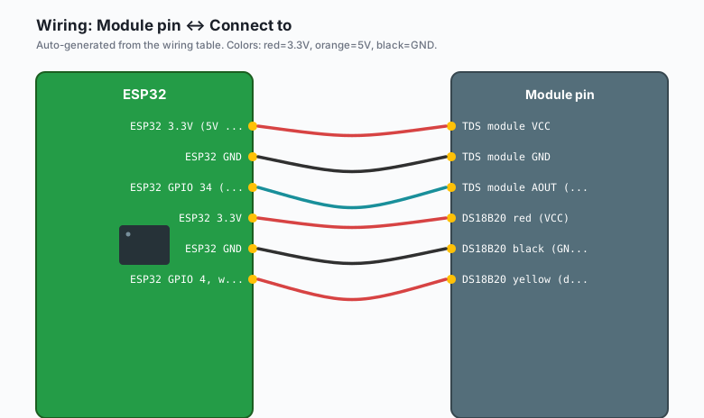
| Module pin | Connect to |
|---|---|
TDS module VCC | ESP32 3.3V (5V also works; see blockquote) |
TDS module GND | ESP32 GND |
| TDS module AOUT (analog) | ESP32 GPIO 34 (ADC1, input-only) |
DS18B20 red (VCC) | ESP32 3.3V |
DS18B20 black (GND) | ESP32 GND |
DS18B20 yellow (data) | ESP32 GPIO 4, with 4.7k pull-up to 3.3V |
The module accepts 3.3 to 5.5V and has an onboard regulator, so its analog output stays in the 0 to 2.3V window either way: no voltage divider is needed on the ESP32, which is one reason this pairing is friendly. The pin that actually matters is the ADC choice: GPIO 34 is ADC1 and input-only, which keeps working while Wi-Fi is on. Never pick an ADC2 pin (GPIO 0, 2, 4, 12-15, 25-27) for this module in a Wi-Fi project; the readings go dead the moment the radio starts.
Install
Two libraries, both from the Library Manager: Arduino IDE >> Sketch >> Include Library >> Manage Libraries, search “OneWire” (by Paul Stoffregen) and install it, then search “DallasTemperature” (by Miles Burton) and install that too. The TDS module needs no library; the conversion is a few lines of math, and keeping it in the sketch means you can see and adjust every constant.
The code
The signal chain: the probe is two electrodes; dissolved ions conduct between them; the module turns that conductivity into a 0-2.3V signal; the ADC samples the voltage; the code converts voltage to TDS in ppm with a temperature correction. Every step in that chain has a known trap, and this sketch handles all of them.
#include <OneWire.h>
#include <DallasTemperature.h>

// --- TDS module ---
#define TDS_PIN 34         // ADC1, input-only, Wi-Fi-safe
#define ADC_RANGE 4095.0   // ESP32 ADC full scale at 12-bit resolution
#define ADC_REF 3.3f       // the ESP32 ADC reference, NOT the 5.0V the
                           // Arduino sample code assumes

// --- DS18B20 ---
#define TEMP_PIN 4
OneWire oneWire(TEMP_PIN);
DallasTemperature tempSensor(&oneWire);

// Median filter: 30 samples, throw away noise spikes
const int SAMPLES = 30;
int buf[SAMPLES];
int bufIdx = 0;

// 1-point calibration factor, set from the calibration step below.
// 1.0 means "as computed"; adjust after comparing to a reference meter.
float calFactor = 1.0;

float readTdsVoltage() {
  // Collect samples with a small gap (the ADC needs settle time and
  // the electrode signal carries mains hum that a median rejects)
  for (int i = 0; i < SAMPLES; i++) {
    buf[bufIdx] = analogRead(TDS_PIN);
    bufIdx = (bufIdx + 1) % SAMPLES;
    delay(40);
  }
  int sorted[SAMPLES];
  memcpy(sorted, buf, sizeof(sorted));
  for (int i = 0; i < SAMPLES - 1; i++)
    for (int j = i + 1; j < SAMPLES; j++)
      if (sorted[j] < sorted[i]) { int t = sorted[i]; sorted[i] = sorted[j]; sorted[j] = t; }
  int median = sorted[SAMPLES / 2];
  return median * (ADC_REF / ADC_RANGE);
}

float tdsFromVoltage(float volts, float tempC) {
  // Temperature compensation: electrode conductivity shifts ~2%/degC.
  // 25 degC is the reference temperature the curve is calibrated at.
  float compensation = 1.0 + 0.02 * (tempC - 25.0);
  float v = volts / compensation;
  // The official curve from the module's reference design (single
  // quadratic, valid over the 0-2.3V output range):
  float tds = (133.42f * v * v - 255.86f * v + 859.39f) * v * 0.5f;
  return tds * calFactor;
}

void setup() {
  Serial.begin(115200);
  analogReadResolution(12);     // 0..4095
  analogSetAttenuation(ADC_11db);   // full 0-3.3V input window
  tempSensor.begin();
  memset(buf, 0, sizeof(buf));
}

void loop() {
  tempSensor.requestTemperatures();
  float tempC = tempSensor.getTempCByIndex(0);
  if (tempC == DEVICE_DISCONNECTED_C) tempC = 25.0;  // sane default

  float volts = readTdsVoltage();
  float ppm = tdsFromVoltage(volts, tempC);

  Serial.print("V: ");     Serial.print(volts, 3);
  Serial.print("  T: ");   Serial.print(tempC, 1);
  Serial.print("  TDS: "); Serial.print(ppm, 0);
  Serial.println(" ppm");
  delay(2000);
}
Sanity checks worth doing once, with a multimeter if you have one: on the official curve, the reading at 0.25V is about 100 ppm and the curve crosses 1000 ppm near 2.15V (the module’s hard output maximum is 2.3V, about 1120 ppm on paper, but 1000 ppm is the advertised range). If your printed volts in distilled water sit well above 0.1V with the probe clean, suspect the probe or the wiring, not the math.
What the numbers mean in practice (the module’s hard range is 0 to 1000 ppm, set by its op-amp output stage):
- 0-50 ppm: essentially distilled / RO water
- 50-200 ppm: clean tap water (varies wildly by city)
- 200-400 ppm: typical hydroponic nutrient solution for leafy greens
- 600+ ppm: getting brackish; alarm territory for most plants
- The absolute value matters less than the trend. A jump from 180 to 400 ppm in one day is a real event (e.g. fertilizer spill, filter exhaustion) even if both numbers look fine in isolation.
Calibration, the step people skip
- Get a reference: a pocket TDS meter or a solution of known ppm.
- Run this sketch in the reference solution at a stable temperature.
- Compare printed ppm to the reference. Set
calFactor = reference / printedand re-flash. (e.g. printed 320, reference 342: calFactor = 1.07) - Re-check in a second liquid (tap water) to confirm the factor holds.
Expect a few percent of drift between calibrations. The electrode coating changes slowly over weeks of immersion; re-check monthly if the number matters.
What you learned
- TDS measures total dissolved solids in ppm; it is a trend sensor, not a safety certification.
- The probe is a conductivity cell; the module outputs 0-2.3V (fixed by hardware, 0-1000 ppm range), and the conversion is one quadratic with a temperature compensation factor.
- The two ESP32-specific traps are the ADC reference (3.3V, not the 5V the Arduino sample assumes) and ADC2 dying when Wi-Fi turns on; GPIO 34 (ADC1) sidesteps both.
- A 30-sample median filter plus a one-point calibration factor gets a $10 probe within a few percent of a $30 hand-held meter.
When something breaks
- Reading stuck near 0 ppm. The probe tip is dry, or AOUT is not actually connected to GPIO 34 (input-only pins read floating without a connection and can sit anywhere). Submerge the probe past the electrode slots, confirm the wire, and confirm VCC/GND with a multimeter.
- Reading stuck near maximum. The probe electrodes are shorted (probe tip touching metal, or the pigtail’s wires pinched together). Lift the probe out of the liquid and confirm the reading falls toward 0; if it stays high, inspect the pigtail.
- ppm changes every time you move the probe. That is partly real
(concentration gradients exist in a glass) and partly noise. Stir
gently before comparing readings, and keep the 30-sample median
filter intact; single
analogRead()calls on the ESP32 bounce by dozens of counts. - Readings changed when Wi-Fi connected. You are on an ADC2 pin. Move the signal wire to GPIO 32, 33, 34, 35, 36, or 39 (all ADC1) and re-flash. This is the most common ESP32-specific TDS failure.
- Readings about double what a hand-held meter says. The ADC
reference in the conversion is wrong (the Arduino Uno sample’s 5.0V
assumption ported unchanged). Set
ADC_REFto 3.3, confirmanalogReadResolution(12), then run the calibration step. - Readings drift through the day with no water changes. Temperature compensation is missing or the water temperature is changing fast (sunlight on a reservoir). Check that the DS18B20 reads sane values and keep the probe shaded; a 10 degree C swing without compensation is about a 20% ppm error.
- Numbers slowly creep up over weeks with stable water. Electrode fouling (mineral film on the probe tip). Clean gently with a soft toothbrush and white vinegar, rinse, and re-run the calibration check.
What to build next
- The plant monitor tutorial is the natural pairing: soil moisture plus reservoir TDS in one device, with watering decisions that respect both numbers.
- The ntfy notifications tutorial pushes a phone alert when ppm leaves the band you set (e.g. hydroponic reservoir drift).
- The MQTT publish/subscribe tutorial streams readings into Home Assistant or another self-hosted dashboard for long-term trending, which is where TDS data actually becomes useful.
- The deep sleep tutorial matters here: the probe electrodes polarize if powered continuously, so a battery device that wakes, samples, reports, and sleeps gives both longer battery life and cleaner numbers. (The Arduino TDS tutorial covers the same module on a 5V board if you are not on ESP32.)