ESP32: drive a NEMA 17 stepper motor with the A4988 driver
Wire a NEMA 17 stepper motor to an ESP32 using the A4988 stepper driver. The right call for real torque and precise positioning.
The NEMA 17 stepper motor is the workhorse for any project that needs real torque and precise positioning: 3D printers, CNC machines, camera sliders, focus stacks. Pair it with the A4988 driver and an ESP32, and you have a motion control system that can lift a kilogram of payload while holding position with no jitter.
This tutorial covers the wiring, the basic stepping code, microstepping for smoother motion, and the current-limiting setup that keeps the A4988 from burning out.
What you need
- ESP32 dev board
- NEMA 17 stepper motor (the standard is 1.8 degree per step, 200 steps per revolution, but check the datasheet for your motor)
- A4988 stepper driver carrier board (the Pololu A4988 is the original; many clones work fine but check the chip markings)
- 100uF electrolytic capacitor (for across the motor power supply)
- External 12V or 24V power supply rated for the stepper (NEMA 17s are typically 12V, 1.5 A per phase)
The ESP32’s 3.3V GPIO cannot drive the A4988’s 5V logic directly. Most A4988 boards have a 3.3V-compatible logic input (the Pololu board does), but check yours. If the board is 5V-only, add a level shifter.
Wiring
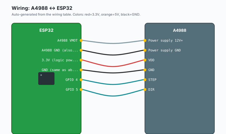
Power supply 12V+ --- A4988 VMOT
Power supply GND --- A4988 GND (also ESP32 GND)
A4988 1B          --- stepper coil 1 (one wire of the first coil)
A4988 1A          --- stepper coil 1 (the other wire of the first coil)
A4982 2A          --- stepper coil 2 (one wire of the second coil)
A4982 2B          --- stepper coil 2 (the other wire of the second coil)
A4988 VDD         --- ESP32 3.3V (logic power)
A4988 GND         --- ESP32 GND (same as above)
A4988 STEP        --- ESP32 GPIO 4
A4988 DIR         --- ESP32 GPIO 5
A4988 EN          --- ESP32 GPIO 16 (optional, active low to enable)
A4988 MS1         --- ESP32 GPIO 17 (optional, microstepping)
A4988 MS2         --- ESP32 GPIO 18 (optional, microstepping)
A4988 MS3         --- ESP32 GPIO 19 (optional, microstepping)
The stepper has two coils, four wires. The pair ordering matters; if you swap a pair, the motor will not spin smoothly. The datasheet for your specific motor tells you which colors are which pair. Most NEMA 17s use A+ (black or red), A- (green or yellow), B+ (blue), B- (white or yellow).
The 100uF capacitor across the motor power supply is not optional. The A4988 switches the motor coils at high frequency, and without bulk capacitance the supply voltage will spike, which can reset the ESP32 or damage the A4988.
Current limiting (the part that saves the motor)
The A4988 delivers up to 2 A per coil without a heatsink. Most NEMA 17s are rated for 1.5-1.7 A. Running the A4988 at full current will overheat the chip and the motor.
You set the current limit with the small potentiometer on the A4988 board. The formula:
V_ref = I_limit * 8 * R_senseFor the Pololu A4988 with the typical R_sense of 0.1 ohm:
| Desired current | V_ref |
|---|---|
| 0.5 A | 0.40 V |
| 1.0 A | 0.80 V |
| 1.5 A | 1.20 V |
| 2.0 A | 1.60 V |
To set it: power the A4988 (motor power on, logic power on), connect a multimeter between the pot wiper and ground, and turn the pot until the voltage reads the value from the table. Use a non-conductive screwdriver (plastic or ceramic) so you do not short anything.
Test without a motor connected first. The A4988 will get hot at high currents; check it after a few minutes and add a heatsink if needed.
The code
const int STEP_PIN = 4;
const int DIR_PIN = 5;
const int STEPS_PER_REV = 200;   // 1.8 degree stepper

void setup() {
  pinMode(STEP_PIN, OUTPUT);
  pinMode(DIR_PIN, OUTPUT);
}

void stepOnce() {
  digitalWrite(STEP_PIN, HIGH);
  delayMicroseconds(10);   // A4988 needs at least 1 us pulse width
  digitalWrite(STEP_PIN, LOW);
  delayMicroseconds(1000);  // 1 ms between steps = 1000 steps/sec
}

void rotate(int steps) {
  if (steps < 0) {
    digitalWrite(DIR_PIN, LOW);
    steps = -steps;
  } else {
    digitalWrite(DIR_PIN, HIGH);
  }
  for (int i = 0; i < steps; i++) {
    stepOnce();
  }
}

void loop() {
  rotate(STEPS_PER_REV);   // one full turn clockwise
  delay(1000);
  rotate(-STEPS_PER_REV);  // one full turn counter-clockwise
  delay(1000);
}
Upload. The stepper should turn one full revolution, pause, turn the other way.
Microstepping for smooth motion
At full step (no microstepping), the motor moves in 1.8 degree jumps. You can hear and feel the discrete steps. Microstepping interpolates between full steps using PWM on the coil currents. The A4988 supports 1, 1/2, 1/4, 1/8, and 1/16 microstepping.
The MS1, MS2, MS3 pins select the mode:
| MS1 | MS2 | MS3 | Mode |
|---|---|---|---|
| LOW | LOW | LOW | Full step |
| HIGH | LOW | LOW | 1/2 step |
| LOW | HIGH | LOW | 1/4 step |
| HIGH | HIGH | LOW | 1/8 step |
| HIGH | HIGH | HIGH | 1/16 step |
For most projects, 1/8 or 1/16 microstepping gives smooth motion at the cost of some torque (microstepping reduces torque by 10-30% per step because both coils are partially energized).
const int MS1_PIN = 17;
const int MS2_PIN = 18;
const int MS3_PIN = 19;

void setup() {
  pinMode(MS1_PIN, OUTPUT);
  pinMode(MS2_PIN, OUTPUT);
  pinMode(MS3_PIN, OUTPUT);

  // 1/8 microstepping
  digitalWrite(MS1_PIN, HIGH);
  digitalWrite(MS2_PIN, HIGH);
  digitalWrite(MS3_PIN, LOW);
}

void rotate(int steps) {
  // Now steps is in 1/8 microsteps, so 1600 per revolution
  // ...
}
Acceleration and deceleration
A stepper that snaps to full speed and then to zero position will miss steps. Add a trapezoidal velocity profile:
void rotateSmooth(int totalSteps, int maxSpeedStepsPerSec) {
  const int accelSteps = 50;   // ramp over 50 steps

  if (totalSteps < 0) {
    digitalWrite(DIR_PIN, LOW);
    totalSteps = -totalSteps;
  } else {
    digitalWrite(DIR_PIN, HIGH);
  }

  for (int i = 0; i < totalSteps; i++) {
    int speed;
    if (i < accelSteps) {
      speed = maxSpeedStepsPerSec * (i + 1) / accelSteps;
    } else if (i > totalSteps - accelSteps) {
      speed = maxSpeedStepsPerSec * (totalSteps - i) / accelSteps;
    } else {
      speed = maxSpeedStepsPerSec;
    }

    if (speed == 0) speed = 1;
    int delayMicros = 1000000 / speed;
    digitalWrite(STEP_PIN, HIGH);
    delayMicroseconds(10);
    digitalWrite(STEP_PIN, LOW);
    delayMicroseconds(delayMicros);
  }
}
This is the basic profile. For real CNC work, use the AccelStepper library on the ESP32 (it has been ported). The library handles acceleration, deceleration, and coordinated multi-motor motion.
The enable pin
The A4988 has an EN (enable) pin. Tie it LOW to enable the driver, HIGH to disable (the motor will freewheel). Most projects tie it to ground permanently. If you want to put the driver in low-power mode between moves, control it from a GPIO:
const int EN_PIN = 16;

void setup() {
  pinMode(EN_PIN, OUTPUT);
  digitalWrite(EN_PIN, LOW);   // enabled
}

void disableMotor() {
  digitalWrite(EN_PIN, HIGH);   // freewheel
}

void enableMotor() {
  digitalWrite(EN_PIN, LOW);    // hold position
}
Disabling between moves saves power but means the motor will not hold position. Enable it again before resuming motion.
What you learned
- NEMA 17 + A4988 is the standard stepper combo for ESP32 motion control.
- The A4988 takes a STEP pulse (one pulse = one step) and a DIR signal (high or low for direction).
- Microstepping smooths motion at the cost of torque.
- Current limiting via the pot is critical to motor life.
When something breaks
- Motor vibrates but does not spin. Coil pairs are wrong. Swap one pair.
- Motor stalls under load. Current limit is too low. Adjust the pot. Or microstepping is too aggressive (1/16 has the least torque).
- A4988 gets very hot. Current limit is too high. Adjust the pot down. Or add a heatsink.
- ESP32 resets when the motor moves. Power supply is undersized or capacitor is missing. The 100uF cap is mandatory.
What to build next
- The servo tutorial is the alternative for low-torque, low-speed positioning. Combine both for projects with mixed motion needs.
- The book ESP32 Robotics Projects covers multi-axis stepper coordination, limit switches, and homing routines.
- The book ESP32 CNC covers GRBL porting to the ESP32 for real CNC control.