ESP32: drive a hobby servo with LEDC
Wire a hobby servo to an ESP32 using the LEDC peripheral. The right way to control an SG90 or MG996R without the Servo.h library.
There are two ways to drive a hobby servo from an ESP32: the Servo.h
library, or the LEDC peripheral directly. The library is easier for the
first 10 minutes. LEDC is the right call for any project with more than
one servo or anything that needs precise PWM control.
This tutorial covers the LEDC way. You learn what the servo signal actually is, how to generate it on any GPIO pin, and why LEDC is better than the Arduino library for projects that scale.
What a hobby servo expects
A hobby servo takes a 50 Hz PWM signal where the pulse width determines the angle:
- 1.0 ms pulse: 0 degrees
- 1.5 ms pulse: 90 degrees
- 2.0 ms pulse: 180 degrees
The pulse repeats every 20 ms (50 Hz). The servo reads the pulse width and moves to the corresponding angle. The full pulse range varies by servo: cheap SG90s are 1000-2000 us, expensive digital servos are 500-2500 us. Check the datasheet for your specific servo.
The LEDC peripheral generates this PWM in hardware, so your code does not
block. You set the duty cycle and the chip does the toggling. This is
the right way to drive multiple servos at once, or any servo where you
need to do other work in loop().
What you need
- ESP32 dev board
- Hobby servo (SG90 is the cheapest, MG996R is the standard pick for real torque)
- 3 jumper wires
- External 5V power supply if the servo needs more than 200 mA (most projects do)
Wiring
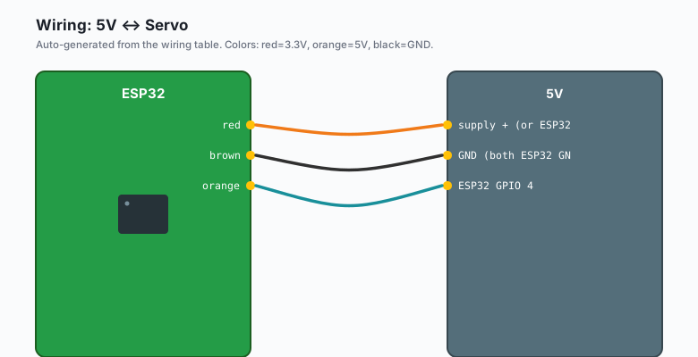
Servo red    -- 5V supply + (or ESP32 5V for SG90 only)
Servo brown  -- GND (both ESP32 GND and supply GND must be connected)
Servo orange -- ESP32 GPIO 4
The brown wire is ground. Connect the servo ground, the ESP32 ground, and the external supply ground together. Without this, the signal reference is floating and the servo will not move.
For an SG90 drawing under 200 mA, you can power it from the ESP32’s 5V pin. For an MG996R or anything bigger, use a separate 5V supply rated for the servo current. The MG996R can draw 1.5 A stall.
The code
const int SERVO_PIN = 4;
const int SERVO_CHANNEL = 0;
const int SERVO_FREQ = 50;       // 50 Hz for servos
const int SERVO_RES = 16;        // 16-bit for fine pulse control

// For SG90 (1.0-2.0 ms range, default digital servo values)
const int SERVO_MIN = 3280;      // ~1.0 ms (0 degrees)
const int SERVO_MID = 4920;      // ~1.5 ms (90 degrees)
const int SERVO_MAX = 6560;      // ~2.0 ms (180 degrees)

void setup() {
  ledcSetup(SERVO_CHANNEL, SERVO_FREQ, SERVO_RES);
  ledcAttachPin(SERVO_PIN, SERVO_CHANNEL);
}

void loop() {
  ledcWrite(SERVO_CHANNEL, SERVO_MIN);
  delay(1000);
  ledcWrite(SERVO_CHANNEL, SERVO_MID);
  delay(1000);
  ledcWrite(SERVO_CHANNEL, SERVO_MAX);
  delay(1000);
}
Upload. The servo should sweep 0, 90, 180 degrees.
Why those magic numbers
The 16-bit resolution at 50 Hz means the period (20 ms) is divided into 65536 steps. Each step is 20 ms / 65536 = 305 ns.
- 1 ms = 1000 us = 1,000,000 ns. 1,000,000 / 305 = 3279. We round to 3280.
- 1.5 ms = 1,500,000 / 305 = 4918. Round to 4920.
- 2 ms = 2,000,000 / 305 = 6557. Round to 6560.
If your servo uses a different pulse range, adjust the constants:
// For a digital servo with 500-2500 us range (huge angle range)
const int SERVO_MIN = 1638;      // ~500 us
const int SERVO_MID = 4920;      // ~1500 us
const int SERVO_MAX = 8192;      // ~2500 us
Driving multiple servos
The LEDC peripheral has 16 channels. Each can drive one servo. Use a different channel per servo:
const int SERVO1_PIN = 4;
const int SERVO2_PIN = 5;
const int SERVO3_PIN = 6;

const int SERVO1_CHANNEL = 0;
const int SERVO2_CHANNEL = 1;
const int SERVO3_CHANNEL = 2;

const int SERVO_MIN = 3280;
const int SERVO_MID = 4920;
const int SERVO_MAX = 6560;

void setup() {
  ledcSetup(SERVO1_CHANNEL, 50, 16);
  ledcAttachPin(SERVO1_PIN, SERVO1_CHANNEL);

  ledcSetup(SERVO2_CHANNEL, 50, 16);
  ledcAttachPin(SERVO2_PIN, SERVO2_CHANNEL);

  ledcSetup(SERVO3_CHANNEL, 50, 16);
  ledcAttachPin(SERVO3_PIN, SERVO3_CHANNEL);
}

void loop() {
  // all three servos sweep in sync
  for (int angle = 0; angle <= 180; angle += 2) {
    int duty = map(angle, 0, 180, SERVO_MIN, SERVO_MAX);
    ledcWrite(SERVO1_CHANNEL, duty);
    ledcWrite(SERVO2_CHANNEL, duty);
    ledcWrite(SERVO3_CHANNEL, duty);
    delay(20);
  }
  // ...
}
This is the pattern for a 4-DOF robotic arm, a 6-DOF hexapod leg, or a pan-tilt camera mount. Up to 16 servos on one ESP32.
A knob-controlled servo (combines with the ADC tutorial)
const int SERVO_PIN = 4;
const int SERVO_CHANNEL = 0;
const int POT_PIN = 34;

void setup() {
  ledcSetup(SERVO_CHANNEL, 50, 16);
  ledcAttachPin(SERVO_PIN, SERVO_CHANNEL);
}

void loop() {
  int raw = analogRead(POT_PIN);
  int duty = map(raw, 0, 4095, 3280, 6560);
  ledcWrite(SERVO_CHANNEL, duty);
  delay(20);
}
Turn the knob, the servo follows. This is the foundation for “knob controls a motor” projects: robotic arm teach pendants, pan-tilt camera positioners, valve controllers.
Smooth motion with ramping
A servo that snaps from 0 to 180 in one step draws a lot of current and might overshoot. Smooth motion looks better and is easier on the mechanics:
int currentAngle = 90;
const int TARGET = 180;
const int STEP = 1;     // 1 degree per loop
const int DELAY = 15;   // ~67 fps

void loop() {
  if (currentAngle < TARGET) {
    currentAngle += STEP;
  } else if (currentAngle > TARGET) {
    currentAngle -= STEP;
  }
  int duty = map(currentAngle, 0, 180, 3280, 6560);
  ledcWrite(SERVO_CHANNEL, duty);
  delay(DELAY);
}
This is the basic motion profile. For real robotics, you want a trapezoidal velocity profile (accel, cruise, decel). That is in the book ESP32 Robotics Projects.
Why not use Servo.h
The Arduino Servo.h library works on the ESP32. It internally uses
LEDC, but with these limitations:
- It uses 8-bit resolution by default. The servo pulse width can vary by ~78 us, which is noticeable on cheap servos.
- It does not let you pick the frequency. It picks 50 Hz, which is right for servos but inflexible.
- Mixing Servo.h with other LEDC channels can cause conflicts.
For one servo in a simple project, Servo.h is fine. For multiple servos, LEDC direct is the right call.
What you learned
- Servos expect a 50 Hz PWM with 1-2 ms pulse widths.
- LEDC generates this on any GPIO pin, in hardware, with no CPU involvement.
- 16-bit resolution at 50 Hz gives ~305 ns precision, more than enough for any servo.
- Up to 16 servos on one ESP32, each on its own LEDC channel.
When something breaks
- Servo jitters. Power issue. Check the supply voltage under load. Add a 100uF capacitor across the servo power pins.
- Servo does not move at all. Wiring is wrong, or the duty cycle
is at a position the servo cannot reach (e.g. outside its physical
range). Test with
SERVO_MIDfirst. - Servo reaches one end and stalls. Pulse width is wrong for your
servo. Adjust
SERVO_MINandSERVO_MAXper the datasheet. - Multiple servos on one supply reset the ESP32. Power supply is undersized. Use a 5V supply rated for the total servo current.
What to build next
- The MPU6050 tutorial combines with this for a self-leveling camera gimbal: MPU6050 reads tilt, two servos correct.
- The HC-SR04 tutorial adds obstacle sensing to a servo-driven robot.
- The book ESP32 Robotics Projects covers multi-servo coordination and motion profiles.