ESP32: control a relay module for switching higher-voltage loads
Use a relay module with an ESP32 to switch mains-powered devices. The hardware safety boundaries and why opto-isolated modules matter.
The relay module is the most useful component for home automation. It lets your ESP32’s 3.3V GPIO switch mains-voltage devices (120/240V AC) and high-current DC loads (12V motors, 24V LED strips). The relay’s coil is driven by the ESP32; the switch contacts are isolated and can carry 10A or more.
This tutorial covers the wiring, the safety rules, and the code. The safety section is not optional. Mains voltage will kill you if you wire it wrong.
What you need
- ESP32 dev board
- 1-channel relay module (5V or 3.3V compatible; about $1-2)
- Jumper wires
The single-channel relay modules are usually labeled:
- VCC - relay coil power (5V on most modules; 3.3V on some)
- GND - ground
- IN or S - signal from the ESP32 GPIO
Use a relay module with opto-isolation. These have a separate power path for the relay coil and the input signal, with an optical isolator chip between them. They are safer than the non-isolated variants because a relay coil failure cannot damage your ESP32.
Wiring
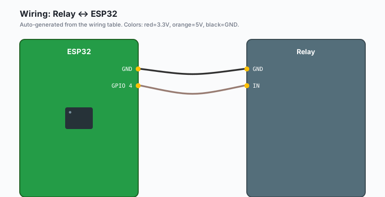
Relay VCC -- ESP32 5V (the relay coil needs more power than the ESP32's 3.3V can supply)
Relay GND -- ESP32 GND
Relay IN  -- ESP32 GPIO 4
If your relay module is labeled “3.3V” on VCC, use the ESP32’s 3.3V pin instead of 5V. Some cheap modules work on either.
Never power the relay from the ESP32’s 3.3V pin if the coil draws more than ~50 mA. The 5V pin (USB-derived) is the right pick.
What you learned (read before the safety section)
The relay’s “switch” side is completely isolated from the “control” side. The ESP32 controls a small coil; the coil’s magnetic field moves a switch inside the relay. The switch contacts can carry mains voltage (120V or 240V AC) or low-voltage DC. The two sides do not electrically connect.
This is what makes relays useful. Your ESP32 stays safe at 3.3V while the load runs at any voltage the contacts are rated for.
Safety: the rules
- Wire mains voltage only when the circuit is unplugged. Turn off the breaker, not just the wall switch.
- Use wire nuts or Wago connectors, not solder, for mains joints. Solder joints on mains wiring can fail over time and arc.
- Use the correct wire gauge. 14 AWG for 15A circuits, 12 AWG for 20A. Lamp cords are 18 AWG and good for 5A.
- Keep mains wiring inside an enclosure. A project box, a junction box, or behind a switch plate. Never leave exposed mains terminals.
- Test with a low-voltage load first. Use a 12V light bulb or a battery-powered fan to verify the wiring before plugging in mains.
Mains voltage kills. If you have not worked with mains before, find someone who has and have them check your wiring before you plug it in. The book ESP32 Smart Home has a longer section on mains safety, including GFCI protection and code compliance.
The code
ESP32 (Arduino)
const int RELAY_PIN = 4;

void setup() {
  pinMode(RELAY_PIN, OUTPUT);
  digitalWrite(RELAY_PIN, LOW);   // relay off (active HIGH relay)
}

void loop() {
  digitalWrite(RELAY_PIN, HIGH);   // relay on
  delay(3000);
  digitalWrite(RELAY_PIN, LOW);    // relay off
  delay(3000);
}
Most relay modules are active LOW: the relay is on when the IN pin is LOW. If your relay turns on when you expect it off and vice versa, swap to
digitalWrite(RELAY_PIN, !state).
Arduino (Uno, Nano, Mega)
const int RELAY_PIN = 4;

void setup() {
  pinMode(RELAY_PIN, OUTPUT);
  digitalWrite(RELAY_PIN, LOW);
}

void loop() {
  digitalWrite(RELAY_PIN, HIGH);
  delay(3000);
  digitalWrite(RELAY_PIN, LOW);
  delay(3000);
}
Same code. The Uno’s 5V GPIO has no ADC2-vs-Wi-Fi trap, so any digital pin works.
Active HIGH vs Active LOW relay
Most cheap relay modules are active LOW: pulling the IN pin LOW turns the relay on. This is because the optocoupler’s transistor turns on when current flows through it (which requires the IN pin to be LOW on most boards).
To check:
const int RELAY_PIN = 4;

void setup() {
  pinMode(RELAY_PIN, OUTPUT);
  Serial.begin(115200);
  Serial.println("Testing relay polarity");
  Serial.println("Relay should click in 5 seconds");
  delay(5000);
  digitalWrite(RELAY_PIN, HIGH);
  Serial.println("Pin HIGH. Listen for click.");
  delay(5000);
  digitalWrite(RELAY_PIN, LOW);
  Serial.println("Pin LOW. Listen for click.");
  delay(5000);
}

void loop() {}
When the relay clicks is your “on” state.
Switching a lamp (mains)
The standard home automation pattern:
- Cut the hot wire (black in the US, brown in the EU) of the lamp.
- Connect one end to the relay’s COM (common) terminal.
- Connect the other end to the relay’s NO (normally open) terminal.
- The neutral wire goes straight through (do not switch neutral).
When the relay activates, COM connects to NO and the lamp gets hot. When the relay deactivates, COM is open and the lamp is off.
The relay also has an NC (normally closed) terminal. This is the opposite: the circuit is closed when the relay is off. Useful for “fail-on” applications (e.g. a heater that should be on if the controller dies).
Switching a 12V LED strip
For low-voltage DC loads:
- Cut the +12V wire of the LED strip.
- Connect one end to COM, the other to NO.
- The relay’s switch contacts handle the 12V; the coil side handles the 5V logic from the ESP32.
The relay contacts are rated for 10A at 125V AC or 10A at 28V DC. For higher current or voltage, use a contactor (a heavy-duty relay).
The contact bounce problem
Mechanical relay contacts bounce, just like buttons. For most projects (driving a lamp, a heater, a motor) this does not matter because the mechanical inertia of the load is slower than the bounce. For fast switching (e.g. PWM-like control of a heater), the bounce causes problems. Use a solid-state relay (SSR) instead.
What you learned
- Relay modules are opto-isolated for safety.
- Most modules are active LOW.
- The control side is safe to wire from the ESP32.
- The switch side can carry mains voltage with the right precautions.
When something breaks
- Relay clicks but the load does not turn on. Load is wired to NC instead of NO (or vice versa). Swap the wire.
- Relay never clicks. Wrong VCC (using 3.3V when the module needs 5V), or IN pin is wrong.
- ESP32 resets when the relay clicks. Coil is drawing too much current. Add a separate 5V supply for the relay.
- Relay stays on all the time. Wrong active level (HIGH vs LOW). Invert the logic.
What to build next
- The PIR motion tutorial combines with this for motion-activated lighting.
- The ESP32 MQTT tutorial lets you turn the relay on from your phone.
- The book ESP32 Smart Home covers mains wiring in detail, with enclosure design and code compliance.