ESP32: drive an SSD1306 OLED display over I2C
Wire a 128x64 OLED display (SSD1306) to an ESP32 and draw text, graphics, and sensor graphs. Smaller and brighter than the 16x2 LCD.
The SSD1306 OLED display is the upgrade path from the 16x2 LCD. Same I2C wiring (2 wires), but you get 128x64 pixels of graphics instead of 32 fixed characters. The text is sharper, the contrast is higher, and you can draw graphs, icons, and animation.
This tutorial covers the wiring, the library, drawing text and shapes, and the patterns for sensor dashboards.
What you need
- ESP32 dev board
- 128x64 SSD1306 OLED module (the kind with 4 pins: VCC, GND, SDA, SCL; about $3-5)
- 4 jumper wires
Wiring
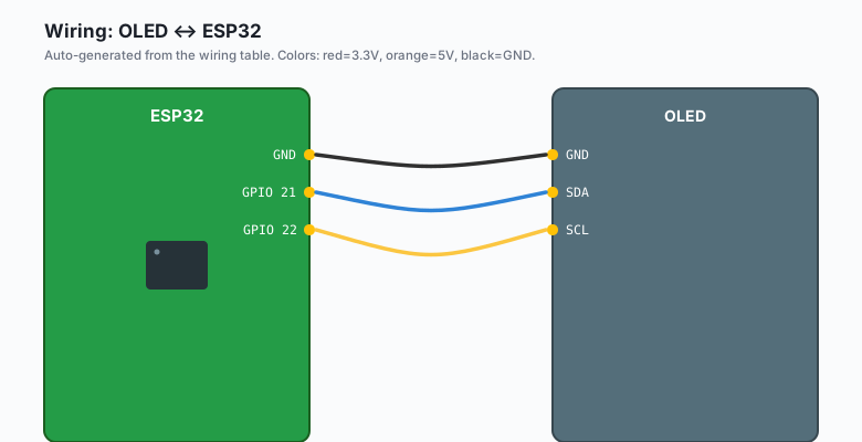
OLED VCC -- ESP32 3.3V (NOT 5V; SSD1306 is 3.3V)
OLED GND -- ESP32 GND
OLED SDA -- ESP32 GPIO 21
OLED SCL -- ESP32 GPIO 22
Some OLED modules have a voltage regulator on the back and accept 5V on VCC. Most do not. Check the back of your module. If the chip is directly on the PCB with no regulator, use 3.3V.
Install libraries
Sketch >> Include Library >> Manage Libraries >> search for
Adafruit SSD1306. Install it. Also install Adafruit GFX Library
when prompted (it is a dependency).
The code
ESP32 (Arduino)
#include <Wire.h>
#include <Adafruit_GFX.h>
#include <Adafruit_SSD1306.h>

#define SCREEN_WIDTH 128
#define SCREEN_HEIGHT 64
Adafruit_SSD1306 display(SCREEN_WIDTH, SCREEN_HEIGHT, &Wire, -1);

void setup() {
  Wire.begin();
  if (!display.begin(SSD1306_SWITCHCAPVCC, 0x3C)) {
    Serial.println("OLED not found");
    while (1);
  }
  display.clearDisplay();
  display.setTextSize(1);
  display.setTextColor(SSD1306_WHITE);
  display.setCursor(0, 0);
  display.println("Hello, ESP32!");
  display.println("OLED works");
  display.display();
}

void loop() {
}
Arduino (Uno, Nano, Mega)
#include <Wire.h>
#include <Adafruit_GFX.h>
#include <Adafruit_SSD1306.h>

#define SCREEN_WIDTH 128
#define SCREEN_HEIGHT 64
Adafruit_SSD1306 display(SCREEN_WIDTH, SCREEN_HEIGHT, &Wire, -1);

void setup() {
  Wire.begin();
  if (!display.begin(SSD1306_SWITCHCAPVCC, 0x3C)) {
    Serial.println("OLED not found");
    while (1);
  }
  display.clearDisplay();
  display.setTextSize(1);
  display.setTextColor(SSD1306_WHITE);
  display.setCursor(0, 0);
  display.println("Hello, Arduino!");
  display.println("OLED works");
  display.display();
}

void loop() {
}
Same code as ESP32. The Adafruit library uses Wire.begin() with the board’s default I2C pins.
MicroPython (ESP32 or Pico)
from machine import I2C, Pin
import ssd1306
import time

# ESP32: GPIO 21 (SDA), 22 (SCL)
# Pico: GPIO 0 (SDA), 1 (SCL)
i2c = I2C(0, scl=Pin(22), sda=Pin(21), freq=400_000)
devices = i2c.scan()
print(f'I2C devices: {[hex(d) for d in devices]}')

oled = ssd1306.SSD1306_I2C(128, 64, i2c, addr=0x3C)
oled.text('Hello, MicroPython!', 0, 0)
oled.text('OLED works', 0, 16)
oled.show()

while True:
    time.sleep(1)
For the Pico, copy
ssd1306.pyfrom https://github.com/micropython/micropython-lib to the Pico’s filesystem.
Raspberry Pi Python
from luma.oled.device import ssd1306
from luma.core.interface.serial import i2c
from PIL import Image, ImageDraw, ImageFont
import time

serial = i2c(port=1, address=0x3C)
device = ssd1306(serial)

with device as d:
    image = Image.new('1', d.size)
    draw = ImageDraw.Draw(image)
    draw.text((0, 0), 'Hello, Pi!', fill=255)
    draw.text((0, 16), 'OLED works', fill=255)
    d.display(image)

time.sleep(1)
Install with pip3 install luma.oled pillow. The luma library uses
PIL for drawing, which is overkill for a static display but useful for
graphics.
What you should see
Upload the ESP32 or Arduino version. The OLED lights up and shows “Hello, ESP32!” on the top line and “OLED works” below it.
If the OLED does not light up at all, the I2C address might be 0x3D instead of 0x3C. Run a scanner and update.
Drawing graphics
The GFX library supports shapes, lines, and rectangles:
display.clearDisplay();
display.drawRect(0, 0, 128, 64, SSD1306_WHITE);   // border
display.fillRect(10, 10, 30, 20, SSD1306_WHITE);  // filled rect
display.drawCircle(64, 32, 20, SSD1306_WHITE);    // circle
display.drawLine(0, 0, 128, 64, SSD1306_WHITE);   // diagonal line
display.setCursor(10, 50);
display.println("Graphics!");
display.display();
For a sensor dashboard with a graph, push old readings into an array and draw them as a polyline.
Text sizes
The GFX library supports 6 text sizes:
display.setTextSize(1);   // 6x8 pixels per character
display.setTextSize(2);   // 12x16
display.setTextSize(3);   // 18x24
Size 1 fits 21 characters per line on a 128-wide display. Size 2 fits 10 characters. Use size 1 for sensor readings, size 2 for the main label.
The sensor dashboard pattern
The most useful pattern is showing a sensor value with a small graph:
#include <DHT.h>
#include <Wire.h>
#include <Adafruit_GFX.h>
#include <Adafruit_SSD1306.h>

#define DHT_PIN 4
DHT dht(DHT_PIN, DHT22);

Adafruit_SSD1306 display(128, 64, &Wire, -1);

float history[64];   // 64 pixels of history
int historyIdx = 0;

void setup() {
  Wire.begin();
  dht.begin();
  display.begin(SSD1306_SWITCHCAPVCC, 0x3C);
  display.clearDisplay();
}

void loop() {
  float t = dht.readTemperature();
  history[historyIdx] = t;
  historyIdx = (historyIdx + 1) % 64;

  display.clearDisplay();
  display.setTextSize(1);
  display.setCursor(0, 0);
  display.print("Temp: ");
  display.print(t, 1);
  display.println(" C");

  // Draw graph
  for (int x = 0; x < 64; x++) {
    int idx = (historyIdx + x) % 64;
    int y = 63 - (int)((history[idx] - 15) * 4);   // 15-30 C maps to bottom-top
    if (y < 16) y = 16;
    if (y > 63) y = 63;
    display.drawPixel(x + 32, y, SSD1306_WHITE);
  }

  display.display();
  delay(500);
}
This shows the current temperature on the top half and a 64-sample history graph on the bottom. Common pattern for sensor nodes.
What you learned
- The SSD1306 OLED uses I2C (2 wires) and runs on 3.3V.
- The Adafruit SSD1306 + GFX libraries give you text, shapes, and pixel-level drawing.
- Same library works on Arduino and ESP32 with no changes.
- MicroPython and Pi Python have equivalent libraries.
When something breaks
- OLED shows nothing. Wrong I2C address (run a scanner), wrong VCC (5V when it should be 3.3V), or the address is 0x3D not 0x3C.
- OLED shows garbage. I2C bus errors. Check pull-ups.
- OLED is dim or flickers. Add a 100nF capacitor across VCC and GND at the OLED.
- Adafruit library hangs in
begin(). Wire.begin() was not called first.
What to build next
- The I2C LCD tutorial covers the alternative display (text only, larger characters).
- The BME280 tutorial combines with this for a weather display.
- The book ESP32 Smart Home covers full-screen UI design with multiple screens and navigation.