ESP32: drive a 16x2 LCD display with the I2C backpack
Wire a 16x2 character LCD (HD44780 with the PCF8574 I2C backpack) to an ESP32 and show text. The right display for showing sensor readings and menus.
The 16x2 character LCD is the workhorse display for showing text. It is the same chip that has been on Arduino projects since the early 2000s, and it still works. Pair it with the PCF8574 I2C backpack and you need only two wires (SDA, SCL) instead of the 6-10 wires a parallel hookup needs.
This tutorial covers the wiring, the library, displaying text, custom characters, and showing live sensor values.
What you need
- ESP32 dev board (or Arduino Uno/Nano, or Pi, or Pico)
- 16x2 LCD with the I2C backpack (the kind with 4 pins: VCC, GND, SDA, SCL; about $3)
- 4 jumper wires
Wiring
The LCD backpack uses I2C. Same pins as the BME280.
LCD VCC -- ESP32 5V (the LCD is 5V-tolerant)
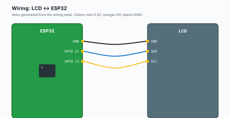
LCD GND -- ESP32 GND
LCD SDA -- ESP32 GPIO 21
LCD SCL -- ESP32 GPIO 22
Some backpacks include a small trimpot for adjusting the contrast. Turn it with a small screwdriver until you can see the text. Most ship with the contrast set too low and you see nothing until you adjust.
The LCD module is 5V. The I2C backpack usually has a pull-up resistor to 5V on SDA and SCL. On the ESP32 (3.3V GPIO), this can damage the pins over time. Add a level shifter, or use a backpack with pull-ups to 3.3V (the Adafruit one has 3.3V pull-ups).
Install libraries
Sketch >> Include Library >> Manage Libraries >> search for
LiquidCrystal_I2C. Install it (there are several variants; the one
by Frank de Brabander works on both ESP32 and Arduino).
The code
ESP32 (Arduino)
#include <Wire.h>
#include <LiquidCrystal_I2C.h>

LiquidCrystal_I2C lcd(0x27, 16, 2);   // address 0x27, 16 cols, 2 rows

void setup() {
  Wire.begin();
  lcd.init();
  lcd.backlight();
  lcd.print("Hello, ESP32!");
  lcd.setCursor(0, 1);
  lcd.print("I2C LCD works");
}

void loop() {
  // Nothing to do
}
Arduino (Uno, Nano, Mega)
#include <Wire.h>
#include <LiquidCrystal_I2C.h>

LiquidCrystal_I2C lcd(0x27, 16, 2);

void setup() {
  Wire.begin();
  lcd.init();
  lcd.backlight();
  lcd.print("Hello, Arduino!");
  lcd.setCursor(0, 1);
  lcd.print("I2C LCD works");
}

void loop() {
  // Nothing to do
}
Same code as ESP32;
Wire.begin()picks the right I2C pins per board (A4/A5 on the Uno, GPIO 21/22 on the ESP32).
MicroPython (ESP32 or Pico)
from machine import I2C, Pin
from esp8266_i2c_lcd1602 import I2cLcd1602
import time

# ESP32: GPIO 21 (SDA), 22 (SCL)
# Pico: GPIO 0 (SDA), 1 (SCL)
i2c = I2C(0, scl=Pin(22), sda=Pin(21), freq=100_000)
devices = i2c.scan()
print(f'I2C devices: {[hex(d) for d in devices]}')

lcd = I2cLcd1602(i2c, 0x27, 2, 16)
lcd.backlight_on()
lcd.puts('Hello, MicroPython!')
lcd.move_to(0, 1)
lcd.puts('I2C LCD works')

while True:
    time.sleep(1)
The
esp8266_i2c_lcd1602library works on both ESP32 and Pico. On the Pico, copy the file from https://github.com/T-622/RPI-PICO-I2C-LCD and rename if needed.
Raspberry Pi Python
from RPLCD.i2c import CharLCD
import time

lcd = CharLCD('PCF8574', 0x27, cols=16, rows=2)
lcd.backlight_enabled = True

lcd.write_string('Hello, Pi!')
lcd.crlf()
lcd.write_string('I2C LCD works')

while True:
    time.sleep(1)
Install with pip3 install RPLCD. Enable I2C on the Pi first:
sudo raspi-config >> Interface Options >> I2C >> Enable.
What you should see
Upload the ESP32 or Arduino version. The LCD lights up blue (backlight) and shows “Hello, ESP32!” on line 1 and “I2C LCD works” on line 2.
If you see nothing but a blue backlight, the contrast pot needs adjustment. Turn it slowly with a screwdriver until text appears.
If the backlight does not turn on, the I2C address might be 0x3F instead of 0x27. Run an I2C scanner sketch and update.
The I2C address
The PCF8574 backpack uses I2C address 0x27 by default. Some boards use
0x3F. If the LCD does not respond to lcd.init(), run an I2C scanner:
#include <Wire.h>

void setup() {
  Serial.begin(115200);
  Wire.begin();
  for (byte addr = 1; addr < 127; addr++) {
    Wire.beginTransmission(addr);
    if (Wire.endTransmission() == 0) {
      Serial.print("Found: 0x");
      Serial.println(addr, HEX);
    }
  }
}

void loop() {}
Use whichever address the scanner finds.
Showing sensor values
The most useful pattern is showing a sensor reading:
#include <DHT.h>
#include <Wire.h>
#include <LiquidCrystal_I2C.h>

#define DHT_PIN 4
DHT dht(DHT_PIN, DHT22);
LiquidCrystal_I2C lcd(0x27, 16, 2);

void setup() {
  Wire.begin();
  dht.begin();
  lcd.init();
  lcd.backlight();
}

void loop() {
  float t = dht.readTemperature();
  float h = dht.readHumidity();

  lcd.setCursor(0, 0);
  lcd.print("T:");
  lcd.print(t, 1);
  lcd.print(" C    ");

  lcd.setCursor(0, 1);
  lcd.print("H:");
  lcd.print(h, 1);
  lcd.print(" %    ");

  delay(2000);
}
The ” ” at the end of each line pads with spaces to clear any leftover characters from the previous update.
Custom characters
You can define up to 8 custom 5x8 pixel characters. Useful for temperature units, degree symbols, or icons:
byte degree[8] = {
  0b00110,
  0b01001,
  0b01001,
  0b00110,
  0b00000,
  0b00000,
  0b00000,
  0b00000
};

void setup() {
  lcd.init();
  lcd.createChar(0, degree);
  lcd.write(byte(0));   // print the degree symbol
}
For most projects, the standard ASCII characters are enough. Custom characters are for the cases where you want a polished UI.
What you learned
- The 16x2 LCD with I2C backpack uses 2 GPIO pins (SDA, SCL).
- The LiquidCrystal_I2C library handles all the I2C details.
- Custom 5x8 characters can be defined with
createChar. - The most useful pattern is showing live sensor readings.
When something breaks
- LCD shows blocks but no text. Contrast pot needs adjustment.
- LCD shows nothing at all. Wrong I2C address (run a scanner), backlight off, or wiring is wrong.
- LCD shows garbage. I2C bus errors. Add pull-up resistors to SDA and SCL (some backpacks are missing them).
- Text flickers. I2C bus is noisy. Add 100nF capacitors across VCC and GND at the LCD.
What to build next
- The OLED tutorial uses a smaller, brighter display with full graphics (vs the LCD’s fixed characters).
- The BME280 tutorial combines with this for a temperature/humidity display.
- The book ESP32 Smart Home covers LCD menu systems for selecting sensor channels.