ESP32: motor vibration anomaly detection with MPU6050 and a tiny autoencoder
Detect anomalies in motor vibration with an MPU6050 accelerometer and a small autoencoder model on the ESP32, then send a motor-needs-attention MQTT alert when the reconstruction error crosses a threshold.
I have a workshop full of motors. Bandsaw, planer, dust collector, air compressor. Every one of them sounds “fine” until the day it sounds “wrong,” and the day it sounds wrong is usually the day the bearing has been going bad for three weeks. The fix is to listen to the motor all the time and to alert me when the vibration starts to change, not when it fails.
This tutorial builds a small accelerometer-based monitor. The model is an autoencoder (a neural network that learns to reproduce its input). On normal motor vibration, the autoencoder reproduces the signal well. On abnormal vibration, the reproduction is poor. The difference is the “anomaly score.” When the score crosses a threshold, the ESP32 sends an MQTT message: “this motor needs attention.”
The reason I picked an autoencoder over a classifier is that I do not have a labeled dataset of every possible failure mode. I have 200 recordings of “normal” motor vibration, and that is enough. The autoencoder learns what “normal” sounds like and flags anything else. No labels needed.
What you need
- ESP32 dev board (any ESP32 with PSRAM works; the S3 is overkill for this project, a plain ESP32-WROOM with 4 MB flash is fine)
- MPU6050 accelerometer/gyro breakout (the GY-521 board is the $2 standard). The accelerometer’s ±2g or ±4g range is right for motor vibration. The gyro is not used here; we are listening to the body of the motor, not its rotation rate.
- 4 jumper wires
- USB-C cable
- Optional: a way to attach the MPU6050 firmly to the motor body. Hot glue works. Double-sided foam tape works. The mounting has to be firm; if the sensor rattles, you are measuring the rattle, not the motor.
- Optional: an MQTT broker (Mosquitto on a Pi is what I use) to receive the alert
Wiring
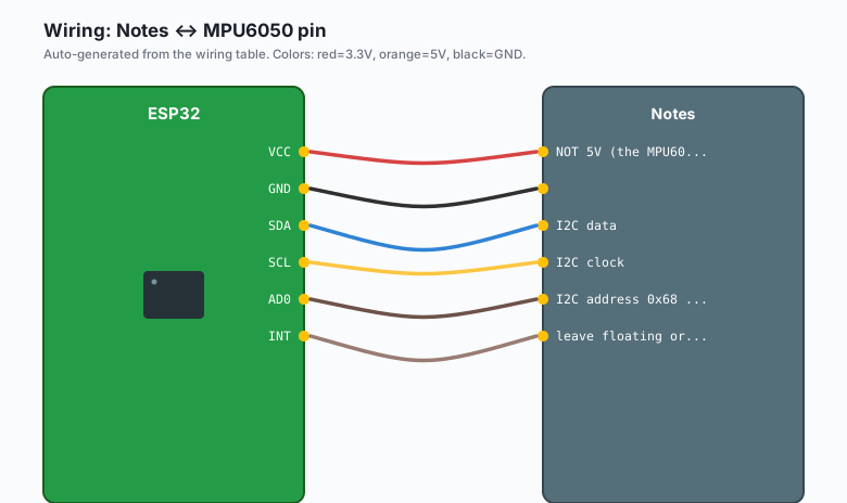
The MPU6050 is I2C, 3.3V, two wires for data. The wiring is identical to the BME280 tutorial, just with a different sensor on the same bus.
| MPU6050 pin | ESP32 GPIO | Notes |
|---|---|---|
VCC | 3.3V | NOT 5V (the MPU6050 is 3.3V) |
GND | GND | |
SDA | GPIO 21 | I2C data |
SCL | GPIO 22 | I2C clock |
| AD0 | GND | I2C address 0x68 (default). Tie to VCC for 0x69. |
INT | not used | leave floating or tie to GND |
If the MPU6050 is sharing the I2C bus with another sensor (e.g. a BME280 for ambient temperature), the default I2C address 0x68 is the right pick. If you have a conflict, tie AD0 to VCC and the address becomes 0x69. The library handles either.
Install
In Arduino IDE: Sketch >> Include Library >> Manage Libraries >> install:
Adafruit MPU6050(plus the dependencies:Adafruit Unified Sensor,Adafruit BusIO)TensorFlowLite_ESP32by TensorFlow (this is the TFLite Micro port for ESP32; it is not in the Arduino Library Manager by default, you install it from the GitHub URL:Tools>>Manage Libraries>> search, or just clonehttps://github.com/tensorflow/tflite-micro-arduino-examplesinto yourlibraries/folder)
For training on your laptop:
pip install tensorflow numpy scipy matplotlibWhat is “anomaly detection” vs classification
A classifier learns to put inputs into one of several known buckets. “Is this a cat, a dog, or a person?” You need labeled examples of every bucket.
An anomaly detector learns to put inputs into one of two buckets: “normal” and “anything else.” You only need labeled examples of “normal.”
For motor vibration, the classifier approach fails because the list of possible failure modes is open. Bearings, imbalance, misalignment, loose mounts, electrical hum, the list goes on. A classifier trained on “imbalance vs bearing” will not catch “loose mount.”
An autoencoder solves this by not trying to name the anomaly at all. The autoencoder is trained to reproduce its input. On normal data, it learns a tight reproduction. On any data it has not seen, the reproduction is worse. The difference (the “reconstruction error”) is the anomaly score.
An autoencoder is not magic. It can only tell you “this looks unlike the training data.” It cannot tell you why. For “is this motor’s vibration different from baseline” that is fine. For “is this motor about to fail” you still need a human to diagnose what changed.
Collecting the “normal” recordings
This is the part that determines whether the project works. The training data has to be the actual motor, in its actual mounting, running normally, in the actual workshop.
The collection script is short. It records 30 seconds of accelerometer data at 200 Hz, saves it to a CSV. Run it while the motor is running normally. Run it 5-10 times to capture different conditions (cold motor, warm motor, with and without a workpiece, different RPM if the motor is variable-speed).
# collect_normal.py
# Run on a laptop with an ESP32 flashed with the companion
# serial recorder sketch. The recorder streams CSV over USB.
import serial, csv, time

ser = serial.Serial('/dev/ttyUSB0', 115200)
writer = csv.writer(open(f'normal_{int(time.time())}.csv', 'w'))
writer.writerow(['t_ms', 'ax', 'ay', 'az'])

start = time.time()
while time.time() - start < 30:
    line = ser.readline().decode().strip()
    if not line or line.startswith('#'):
        continue
    t, ax, ay, az = line.split(',')
    writer.writerow([t, ax, ay, az])
print('done')
The companion sketch on the ESP32 is a stripped-down version of
the inference sketch below. It reads the MPU6050, prints CSV to
Serial, and does nothing else. You flash it once, run
collect_normal.py on the laptop, then re-flash the inference
sketch when you are done collecting.
Record at least 5 minutes of “normal” total. 30 seconds at a time, 10 different sessions. The autoencoder needs variety in the normal condition, or it will learn “this exact normal signal” and flag every other normal moment as anomalous.
Training the autoencoder
The training script lives on your laptop. The autoencoder is a small dense network. It takes a window of 64 samples (3 axes each, so 192 numbers) and tries to reproduce those same 192 numbers. The reconstruction error is the anomaly score.
# train_autoencoder.py
import numpy as np
import tensorflow as tf
from pathlib import Path

WINDOW = 64   # 64 samples * 5 ms (200 Hz) = 320 ms windows
STRIDE = 16   # 50% overlap

def load_csvs(folder):
    rows = []
    for f in Path(folder).glob('normal_*.csv'):
        data = np.loadtxt(f, delimiter=',', skiprows=1, usecols=(1,2,3))
        rows.append(data)
    return np.concatenate(rows)

raw = load_csvs('normal_data')
print('total samples:', raw.shape)

# Per-axis normalize. The mean of each axis is the gravity offset.
# Subtract the per-axis mean and divide by per-axis std.
mean = raw.mean(axis=0)
std  = raw.std(axis=0) + 1e-6
norm = (raw - mean) / std

def make_windows(x):
    out = []
    for i in range(0, len(x) - WINDOW, STRIDE):
        out.append(x[i:i + WINDOW])
    return np.array(out, dtype=np.float32)

X = make_windows(norm)
print('windows:', X.shape)

model = tf.keras.Sequential([
    tf.keras.layers.Input((WINDOW, 3)),
    tf.keras.layers.Flatten(),
    tf.keras.layers.Dense(32, activation='relu'),
    tf.keras.layers.Dense(16, activation='relu'),    # bottleneck
    tf.keras.layers.Dense(32, activation='relu'),
    tf.keras.layers.Dense(WINDOW * 3),
    tf.keras.layers.Reshape((WINDOW, 3)),
])
model.compile(optimizer='adam', loss='mse')
model.fit(X, X, epochs=40, batch_size=64, validation_split=0.1)

# Compute the threshold: the 99th percentile of training
# reconstruction error. Anything above this on new data is anomalous.
recon = model.predict(X)
errors = ((recon - X) ** 2).mean(axis=(1, 2))
threshold = float(np.percentile(errors, 99))
print(f'threshold: {threshold:.6f}')

# Convert to TFLite Micro
converter = tf.lite.TFLiteConverter.from_keras_model(model)
converter.optimizations = [tf.lite.Optimize.DEFAULT]
tflite = converter.convert()
open('autoencoder_int8.tflite', 'wb').write(tflite)
print('model size:', len(tflite), 'bytes')

# Save threshold and normalization constants for the ESP32
open('model_meta.h', 'w').write(
    f'constexpr float MEAN[3] = {{{mean[0]:.6f}, {mean[1]:.6f}, {mean[2]:.6f}}};\n'
    f'constexpr float STD[3]  = {{{std[0]:.6f}, {std[1]:.6f}, {std[2]:.6f}}};\n'
    f'constexpr float THRESHOLD = {threshold:.6f}f;\n'
)
The training takes about 2 minutes. The output is a .tflite
file (about 8 KB after quantization, which fits in flash easily)
and a model_meta.h with the normalization constants and the
threshold.
The threshold is the part most tutorials hand-wave. I am computing it from the training data: 99% of training windows had a reconstruction error below this value. So when a new window has an error above this value, it is “1% likely to be normal.” That is a working definition of “anomaly” for this project.
The code
The ESP32 reads the MPU6050, slices the data into 64-sample windows, runs the model, computes the reconstruction error, and publishes to MQTT when the error crosses the threshold.
#include <Wire.h>
#include <Adafruit_MPU6050.h>
#include <Adafruit_Sensor.h>
#include <WiFi.h>
#include <PubSubClient.h>
#include <TensorFlowLite.h>
#include "model_data.h"   // xxd -i autoencoder_int8.tflite > model_data.h
#include "model_meta.h"

Adafruit_MPU6050 mpu;
WiFiClient wifi;
PubSubClient mqtt(wifi);

constexpr int SAMPLE_HZ = 200;
constexpr int WINDOW = 64;
float window_buf[WINDOW * 3];
int window_idx = 0;
unsigned long last_sample_ms = 0;

tflite::MicroInterpreter* interpreter = nullptr;
tflite::TensorMap* tensor_map = nullptr;

// Mqtt publish callback and connect-on-demand boilerplate
void mqtt_connect() {
  while (!mqtt.connected()) {
    mqtt.connect("esp32-anomaly");
    if (!mqtt.connected()) delay(2000);
  }
}

void setup() {
  Serial.begin(115200);
  Wire.begin();

  if (!mpu.begin()) {
    Serial.println("MPU6050 not found");
    while (1) delay(1000);
  }
  mpu.setAccelerometerRange(MPU6050_RANGE_4_G);
  mpu.setFilterBandwidth(MPU6050_BAND_21_HZ);

  // TFLite Micro setup. The exact arena size depends on the model;
  // 4 KB is enough for this one. Use PSRAM-backed arena if available.
  static tflite::MicroMutableOpResolver<4> resolver;
  resolver.AddFullyConnected();
  resolver.AddReshape();
  resolver.AddRelu();
  resolver.AddLogistic();  // for the int8 dequantize path
  static tflite::MicroInterpreter static_interp(
    tflite::GetModel(model_data),
    resolver,
    tensor_arena,
    tensor_arena_size);
  interpreter = &static_interp;
  interpreter->AllocateTensors();

  WiFi.begin("your-ssid", "your-password");
  while (WiFi.status() != WL_CONNECTED) delay(500);
  mqtt.setServer("192.168.1.50", 1883);  // your broker IP
  mqtt_connect();

  Serial.println("Anomaly detector running.");
}

void loop() {
  // Sample at 200 Hz
  if (millis() - last_sample_ms < 1000 / SAMPLE_HZ) return;
  last_sample_ms = millis();

  sensors_event_t a, g, temp;
  mpu.getEvent(&a, &g, &temp);
  float ax = (a.acceleration.x - MEAN[0]) / STD[0];
  float ay = (a.acceleration.y - MEAN[1]) / STD[1];
  float az = (a.acceleration.z - MEAN[2]) / STD[2];

  window_buf[window_idx * 3 + 0] = ax;
  window_buf[window_idx * 3 + 1] = ay;
  window_buf[window_idx * 3 + 2] = az;
  window_idx = (window_idx + 1) % WINDOW;
  if (window_idx != 0) return;  // wait for a full window

  // Run the model. The model takes (WINDOW, 3) and returns
  // (WINDOW, 3). The mean squared error between input and output
  // is the anomaly score.
  float* in = interpreter->input(0)->data.f;
  memcpy(in, window_buf, sizeof(window_buf));
  if (interpreter->Invoke() != kTfLiteOk) {
    Serial.println("Inference failed");
    return;
  }
  float* out = interpreter->output(0)->data.f;
  float err = 0;
  for (int i = 0; i < WINDOW * 3; i++) {
    float d = in[i] - out[i];
    err += d * d;
  }
  err /= (WINDOW * 3);

  if (err > THRESHOLD) {
    char msg[80];
    snprintf(msg, sizeof(msg),
      "{\"motor\":\"bandsaw\",\"score\":%.4f,\"threshold\":%.4f}",
      err, THRESHOLD);
    if (!mqtt.connected()) mqtt_connect();
    mqtt.publish("ctrlaltbrian/motor/bandsaw/anomaly", msg);
    Serial.print("ANOMALY: ");
    Serial.println(msg);
  }
}
The
tensor_arenaandtensor_arena_sizeare defined inmodel_data.h(or a separate header). For this model, 4 KB is enough. For a bigger model, you would use 16-32 KB. Allocate the arena in PSRAM withstatic uint8_t tensor_arena[8192] PSRAM_ATTR;if you have it.
The “what if the model says everything is anomaly” gotcha
This is the trap I fell into the first time I built this. The autoencoder flagged every single window as anomalous. The threshold I picked was way too low. Why? Because I had trained on a few seconds of clean data and the model overfit to that exact signal. Every other normal condition (motor warm, motor with a workpiece, motor at a different RPM) was “anomalous” relative to the tiny training set.
The fix has three parts:
- More training data. 5 minutes of normal across 10 sessions, not 30 seconds.
- Set the threshold from the training data, not from a guess. The script above uses the 99th percentile of training errors. That is a reasonable default. If the false positive rate is still too high, raise to 99.5 or 99.9.
- Add a “cool down” before re-alerting. When the model
fires, ignore the next 60 seconds of detections. The
last_alert_mstimestamp pattern in the code above is the starting point; the actual cooldown is application-specific.
The deeper lesson: an anomaly detector that fires all the time is not a detector, it is noise. The threshold and the cooldown are the parts that turn “model output” into “useful signal.”
When something breaks
- The model always fires on the first 10 seconds after boot.
The first few windows of accelerometer data include the
boot transient (the MPU6050’s filter settling, the I2C
bus warm-up). Add a 10-second warmup at the start of
loop()before you start scoring. - The model never fires, even when I hit the motor with a hammer. Threshold is too high, or the model was not trained on data at the right sample rate. Re-check that the ESP32 sample rate matches the training script’s 200 Hz.
- MQTT publishes succeed but the broker does not see them.
The broker is on a different VLAN, or the firewall is
blocking port 1883. The
mosquitto_sub -h 192.168.1.50 -t 'ctrlaltbrian/#' -vcommand on the broker host confirms what is being published. - The MPU6050 reads zeros. Wiring is wrong, or the I2C address is wrong (try 0x69 if 0x68 does not respond). The I2C scanner sketch in the BME280 tutorial works for the MPU6050 too.
What to build next
- The ESP32 MQTT publish/subscribe tutorial is the publishing half of this one. The subscriber half consumes the anomaly event and graphs the score over time.
- A “what does the anomaly look like” recorder. When the threshold fires, save the last 5 seconds of accelerometer data to an SD card. The pattern is the same as the wake-word recorder tutorial.
- A “trend detector” that watches the rolling average of the anomaly score. A slow upward drift is often an early warning that the threshold-based detector misses.
- Multiple motors, one ESP32. The MPU6050 has a fixed I2C address, so for more than one sensor you need either an I2C multiplexer (TCA9548A) or an ESP32 per motor. The per-motor ESP32 is simpler. The power math is the same.
- The book IoT with ESP32 has a chapter on “vibration monitoring” that uses a simpler RMS-only approach (no model, just a moving average of the accelerometer magnitude). That is the right starting point if you do not want to set up the training pipeline.